Product Description
Product Specification
Product Display
Related Products
Packaging and Transportation
Customer Photo
Our Certificate
Company Profile
FAQ
FAQ:
1. Q:What’s your best price for this product?
A: We will quote you best price according to your quantity, so when you making an inquiry, please let us know the quantity you want.The more quantity the better price.
2. Q:How about the quality of this product?
A: Our products are certified to ISO9001, TS16949 international quality standards. We compay have very strict Quality Control Systems.
3. Q:What material of the product can you supply?
A: Steel
4. Q:What’s your MOQ?
A: 10pcs for each model. We hope you can buy more to save more money.
5. Q:What’s the delivery time?
A: For products that are in stock, we can ship it within 7 days after receiving your payment. For custom order, quantity within 24 tons, production time is 12-20 days after confirmed every details.
6. Q:What’s your packing?
A:Our usual packing for this product is pallet, we can also supply you packing according to your requirements.
7. Q:Can we custom our own logo or label on this product?
A: Yes, you can. we support logo print & stamping & label print, print will be free if the logo is not very complex.
8. Q:What about the warranty?
A: We are very confident in our products, and we pack them very well to make sure the goods in well protection.
To avoid any subsequent trouble regarding quality issue, we suggest that you check the springs once you receive them. If there is any transport damaged or quality issue, don’t forget take the detail pictrues and contact us as soon as possible,we will properly handle it, make sure your loss to reduce to the smallest .
/* January 22, 2571 19:08:37 */!function(){function s(e,r){var a,o={};try{e&&e.split(“,”).forEach(function(e,t){e&&(a=e.match(/(.*?):(.*)$/))&&1
| After-sales Service: | After Sales Service |
|---|---|
| Condition: | New |
| Application: | Trailer |
| Certification: | CE, ISO |
| Material: | Steel |
| Type: | Front Axles |
| Customization: |
Available
| Customized Request |
|---|

Can you provide insights into the maintenance of axle bearings for smooth operation?
Maintaining axle bearings is essential for ensuring smooth operation, longevity, and optimal performance of a vehicle’s axle system. Here are some insights into the maintenance of axle bearings:
1. Regular Inspection:
Perform regular visual inspections of the axle bearings to check for any signs of wear, damage, or leaks. Look for indications such as excessive play, unusual noises, vibration, or leakage of grease. Inspections should be carried out as per the manufacturer’s recommended intervals or during routine maintenance checks.
2. Lubrication:
Adequate lubrication is crucial for the smooth operation of axle bearings. Follow the manufacturer’s guidelines for the type of lubricant to use and the recommended intervals for greasing. Over-greasing or under-greasing can lead to bearing damage or failure. Ensure that the proper amount of grease is applied to the bearings, and use a high-quality grease that is compatible with the axle bearing specifications.
3. Seal Inspection and Replacement:
Check the condition of the axle bearing seals regularly. The seals help to keep contaminants out and retain the lubricating grease within the bearing. If the seals are damaged, worn, or show signs of leakage, they should be replaced promptly to prevent dirt, water, or debris from entering the bearing assembly and causing damage.
4. Proper Installation:
During axle bearing replacement or installation, it is crucial to follow proper procedures to ensure correct seating and alignment. Improper installation can lead to premature bearing failure and other issues. Refer to the manufacturer’s instructions or consult a professional mechanic to ensure proper installation techniques are followed.
5. Load Capacity and Alignment:
Ensure that the axle bearings are properly sized and rated to handle the load capacity of the vehicle and the specific application. Overloading the bearings can lead to excessive wear and premature failure. Additionally, proper wheel alignment is important to prevent uneven bearing wear. Regularly check and adjust the wheel alignment if necessary.
6. Environmental Considerations:
Take into account the operating conditions and environment in which the vehicle is used. Extreme temperatures, exposure to water, dirt, or corrosive substances can affect the performance of axle bearings. In such cases, additional preventive measures may be necessary, such as more frequent inspections, cleaning, and lubrication.
7. Professional Maintenance:
If you are unsure about performing maintenance on axle bearings yourself or if you encounter complex issues, it is recommended to seek assistance from a qualified mechanic or technician who has experience with axle systems. They can provide expert advice, perform necessary repairs or replacements, and ensure proper maintenance of the axle bearings.
By following these maintenance insights, you can help ensure the smooth operation, longevity, and reliability of axle bearings, contributing to the overall performance and safety of the vehicle.

Where can I purchase high-quality replacement axles for my make and model of vehicle?
When it comes to purchasing high-quality replacement axles for your specific make and model of vehicle, there are several reliable sources you can consider. Here are some options:
- Authorized Dealerships:
- Independent Auto Parts Stores:
- Online Retailers:
- Specialty Performance Retailers:
- Local Salvage Yards:
- Vehicle Manufacturer’s Online Parts Store:
Authorized dealerships of your vehicle’s manufacturer are a trustworthy option for purchasing replacement axles. They offer genuine parts that are specifically designed and engineered for your make and model. Contact your local dealership’s parts department to inquire about the availability of replacement axles.
Independent auto parts stores often carry a wide range of replacement axles from reputable manufacturers. These stores typically have knowledgeable staff who can help you identify the correct axle for your vehicle. Examples of popular auto parts stores include AutoZone, Advance Auto Parts, and O’Reilly Auto Parts.
Online retailers provide a convenient way to browse and purchase replacement axles from the comfort of your home. Websites such as Amazon, eBay, and RockAuto offer extensive selections of axles for various vehicle makes and models. Be sure to verify the compatibility of the axles with your specific vehicle before making a purchase.
If you are looking for high-performance or upgraded axles, specialty performance retailers may be the way to go. These retailers cater to enthusiasts and offer axles that are designed to handle increased power, torque, or off-road demands. Examples of specialty performance retailers include Summit Racing, Jegs, and 4 Wheel Parts.
Salvage yards, also known as junkyards or auto recyclers, can be a cost-effective option for finding used axles in good condition. Some salvage yards have an inventory system that allows you to search for specific parts based on your vehicle’s make and model. It’s important to thoroughly inspect used axles before purchase to ensure they meet your requirements.
Many vehicle manufacturers have their own online parts stores where you can directly purchase genuine replacement parts, including axles. These online stores provide the assurance of authenticity and compatibility with your specific make and model. Visit the official website of your vehicle’s manufacturer and look for their parts store section.
When purchasing replacement axles, it’s important to prioritize quality and ensure that the parts meet or exceed the original equipment specifications. Consider factors such as warranty coverage, customer reviews, and the reputation of the manufacturer or retailer. Additionally, consult with knowledgeable professionals or refer to your vehicle’s owner’s manual for specific axle specifications and recommendations.

What is the primary function of an axle in a vehicle or machinery?
An axle plays a vital role in both vehicles and machinery, providing essential functions for their operation. The primary function of an axle is to transmit rotational motion and torque from an engine or power source to the wheels or other rotating components. Here are the key functions of an axle:
- Power Transmission:
- Support and Load Bearing:
- Wheel and Component Alignment:
- Suspension and Absorption of Shocks:
- Steering Control:
- Braking:
An axle serves as a mechanical link between the engine or power source and the wheels or driven components. It transfers rotational motion and torque generated by the engine to the wheels, enabling the vehicle or machinery to move. As the engine rotates the axle, the rotational force is transmitted to the wheels, propelling the vehicle forward or driving the machinery’s various components.
An axle provides structural support and load-bearing capability, especially in vehicles. It bears the weight of the vehicle or machinery and distributes it evenly across the wheels or supporting components. This load-bearing function ensures stability, balance, and proper weight distribution, contributing to safe and efficient operation.
The axle helps maintain proper alignment of the wheels or rotating components. It ensures that the wheels are parallel to each other and perpendicular to the ground, promoting stability and optimal tire contact with the road surface. In machinery, the axle aligns and supports the rotating components, ensuring their correct positioning and enabling smooth and efficient operation.
In vehicles, particularly those with independent suspension systems, the axle plays a role in the suspension system’s operation. It may incorporate features such as differential gears, CV joints, or other mechanisms that allow the wheels to move independently while maintaining power transfer. The axle also contributes to absorbing shocks and vibrations caused by road irregularities, enhancing ride comfort and vehicle handling.
In some vehicles, such as trucks or buses, the front axle also serves as a steering axle. It connects to the steering mechanism, allowing the driver to control the direction of the vehicle. By turning the axle, the driver can steer the wheels, enabling precise maneuverability and navigation.
An axle often integrates braking components, such as brake discs, calipers, or drums. These braking mechanisms are actuated when the driver applies the brakes, creating friction against the rotating axle or wheels and causing deceleration or stopping of the vehicle. The axle’s design can affect braking performance, ensuring effective and reliable stopping power.
Overall, the primary function of an axle in both vehicles and machinery is to transmit rotational motion, torque, and power from the engine or power source to the wheels or rotating components. Additionally, it provides support, load-bearing capability, alignment, suspension, steering control, and braking functions, depending on the specific application and design requirements.


editor by CX 2024-03-10
China manufacturer Heavy Duty Truck Parts Steel Bearing Wheel Hub for CZPT Hub axle cap
Product Description
Product Description
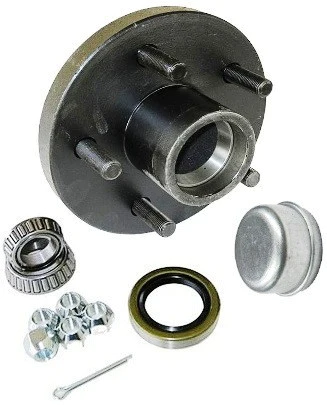
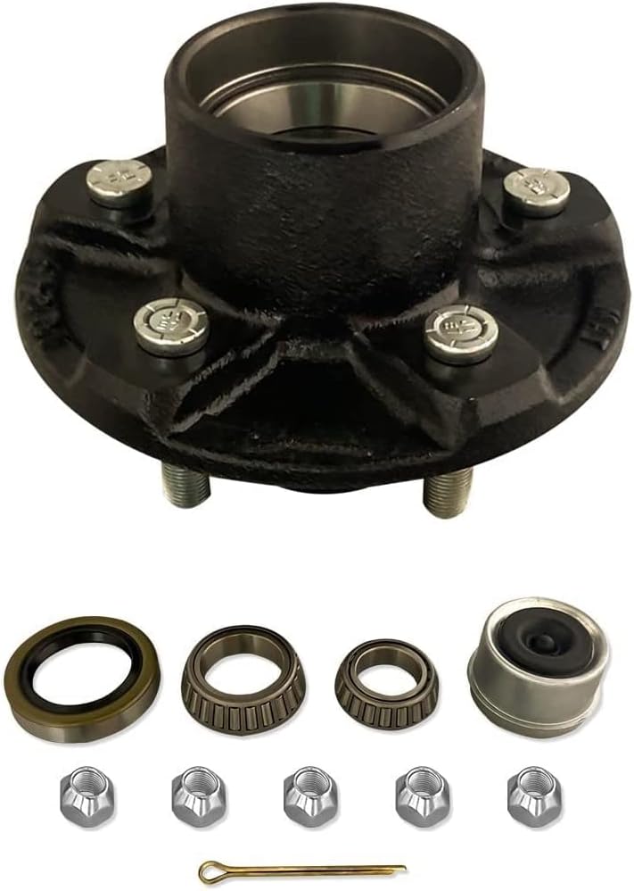
Heavy Duty Truck Parts Steel Bearing Wheel Hub for CZPT Hub
Product Parameters
| MODEL | DIAMETER OF MOUNTING HOLE(A) NO. | DIAMETER OF MOUNTING HOLE(A) SIZE | BOLT DISTRIBUTION DIAMETER | BEARING POSITION | OIL SEAL POSITION | STOP POSITION | INNER SHAFT DISTANCE OF RIM | TOTAL HEIGHT(F) | FLANGE DIAMETER | REMARKS |
| ZYQC-DT-LG | 10 | 22 | 335 | 152.4 152 | 152.8 | 176 | 45 | 165 | 383 | SINGLE WHEEL HUB |
| ZY-10TA002 | 10 | 23 | 225 | 152.4 152.4 | 152.8 | 172 | 32 | 202 | 280 | 10T |
| ZY-13TA002 | 10 | 22 | 335 | 152.4 152.4 | 152.8 | 280 | 45 | 230 | 383 | 13T |
| ZY-16TA002 | 10 | 22 | 335 | 157 152.4 | 160 | 280 | 39 | 230 | 383 | 16T |
| ZY-20TA002 | 10 | 22 | 335 | 200 152.4 | 200.4 | 280 | 16 | 242 | 383 | 20T |
| ZY-25TA002 | 10 | 22 | 335 | 200 200 | 200.4 | 280 | 25 | 257 | 383 | 25T |
| ZY-16TJ001 | 10 | 22 | 335 | 200.2 150.2 | 200.2 | 280 | 23 | 286 | 380 | 16T |
| ZY-WZ16T | 10 | 23 | 225 | 35 170 | 152 | 196 | 20 | 216 | 276 | 16T |
| ZY-6TA002 | 10 | 20 | 222 | 125 110 | 130 | 160 | 41 | 192 | 260 | 6T |
| ZY-DS01 | 10 | 23 | 335 | 152.4 152.4 | 152.8 | 280 | 46 | 230 | 383 | DISC BRAKE HUB |
Workshop
Certifications
Company Profile
Packaging & Shipping
/* January 22, 2571 19:08:37 */!function(){function s(e,r){var a,o={};try{e&&e.split(“,”).forEach(function(e,t){e&&(a=e.match(/(.*?):(.*)$/))&&1
| After-sales Service: | Online Services |
|---|---|
| Warranty: | One Year |
| Type: | Wheel |
| Certification: | ISO/TS16949, CCC, ISO |
| Loading Weight: | Customer Demand |
| ABS: | Customer Demand |
| Samples: |
US$ 45/Piece
1 Piece(Min.Order) | |
|---|
| Customization: |
Available
| Customized Request |
|---|
Can a damaged axle hub affect the overall performance and safety of a vehicle?
Yes, a damaged axle hub can significantly affect the overall performance and safety of a vehicle. Here’s a detailed explanation of how a damaged axle hub can impact a vehicle:
1. Wheel Stability:
A damaged axle hub can compromise the stability of the wheel assembly. If the hub is bent, cracked, or worn out, it may not provide a secure mounting point for the wheel. This can result in wheel wobbling or excessive play, leading to unstable handling and compromised vehicle control. A wobbling wheel can also cause vibrations, which can affect the comfort of the passengers and potentially lead to further damage to other components of the suspension system.
2. Wheel Bearing Performance:
The axle hub houses the wheel bearings, which are critical for smooth wheel rotation and weight support. A damaged axle hub can negatively impact the performance of the wheel bearings. For example, if the hub is misaligned or has damaged bearing races, it can cause excessive friction, uneven wear, and premature failure of the wheel bearings. This can lead to wheel noise, reduced fuel efficiency, and compromised safety as the wheel may seize or detach while driving.
3. Brake System Integration:
In many vehicles, the axle hub integrates with the brake rotor or drum. A damaged axle hub can affect the proper installation and function of the braking components. For example, if the hub has damaged mounting surfaces or incorrect dimensions, it may result in brake rotor runout or misalignment. This can cause uneven braking, pulsation in the brake pedal, and reduced braking performance, compromising the vehicle’s ability to stop safely and efficiently.
4. Wheel Alignment and Suspension:
The axle hub plays a role in maintaining proper wheel alignment and supporting the suspension system. A damaged axle hub can lead to misalignment, affecting the camber, toe, or caster angles of the wheel. Improper wheel alignment can result in uneven tire wear, compromised handling, and reduced stability, impacting overall vehicle performance and safety. Additionally, a damaged hub may not provide adequate support for the suspension components, leading to increased stress and potential failure of other suspension parts.
5. Risk of Wheel Separation:
If a damaged axle hub is not addressed promptly, there is a risk of wheel separation. A severely damaged hub can eventually fail, causing the wheel to detach from the vehicle while in motion. Wheel separation is extremely dangerous and can result in a loss of control, vehicle instability, and potential accidents with severe consequences for the occupants and other road users.
6. Overall Safety:
The overall safety of the vehicle can be compromised when the axle hub is damaged. The stability, braking performance, wheel alignment, and suspension function are critical for safe operation. A damaged axle hub can negatively impact these aspects, increasing the risk of accidents and reducing the ability to control the vehicle effectively.
In summary, a damaged axle hub can have a significant impact on the overall performance and safety of a vehicle. It can compromise wheel stability, impair wheel bearing performance, affect brake system integration, disrupt wheel alignment and suspension, and increase the risk of wheel separation. It is crucial to address any signs of axle hub damage promptly to ensure the safe and efficient operation of the vehicle.
What role does the ABS sensor play in the context of an axle hub assembly?
The ABS (Anti-lock Braking System) sensor plays a crucial role in the context of an axle hub assembly. It is an integral component of the braking system and is responsible for monitoring the speed and rotational behavior of the wheels. Here’s a detailed explanation of the role of the ABS sensor in the context of an axle hub assembly:
- Wheel speed monitoring: The primary function of the ABS sensor is to monitor the rotational speed of the wheels. It does this by detecting the teeth or magnetic patterns on a tone ring or reluctor ring mounted on the axle hub or adjacent to the wheel hub. By continuously measuring the speed of each wheel, the ABS sensor provides crucial data to the vehicle’s ABS system.
- Anti-lock Braking System (ABS): The ABS system utilizes the data provided by the ABS sensors to determine if any wheel is about to lock up during braking. If a wheel is on the verge of locking up, the ABS system modulates the braking pressure to that wheel. This prevents the wheel from fully locking up, allowing the driver to maintain control of the vehicle and reducing the risk of skidding or loss of steering control.
- Traction control: In addition to aiding the ABS system, the ABS sensors also play a role in the vehicle’s traction control system. By continuously monitoring the rotational speed of the wheels, the ABS sensors assist in detecting any wheel slippage or loss of traction. When a wheel slips, the traction control system can adjust the engine power output or apply brake pressure to the specific wheel to regain traction and maintain stability.
- Stability control: Some modern vehicles incorporate stability control systems that rely on the ABS sensors to monitor the rotational behavior of the wheels. By comparing the speeds of individual wheels, the stability control system can detect and mitigate any potential loss of vehicle stability. This may involve applying brakes to specific wheels or adjusting engine power to help the driver maintain control in challenging driving conditions or during evasive maneuvers.
- Diagnostic capabilities: The ABS sensors also provide diagnostic capabilities for the vehicle’s onboard diagnostic system. In the event of a fault or malfunction within the ABS system, the ABS sensors can transmit error codes to the vehicle’s computer, which can then be retrieved using a diagnostic scanner. This aids in the identification and troubleshooting of ABS-related issues.
The ABS sensor is typically mounted near the axle hub, with its sensor tip in close proximity to the tone ring or reluctor ring. It generates electrical signals based on the detected rotational patterns, which are then transmitted to the vehicle’s ABS control module for processing and action.
In summary, the ABS sensor plays a vital role in the context of an axle hub assembly. It monitors the rotational speed of the wheels, providing essential data for the ABS system, traction control, and stability control. The ABS sensor helps prevent wheel lockup during braking, enhances traction in slippery conditions, aids in maintaining vehicle stability, and contributes to the diagnostic capabilities of the ABS system.
Where can I access reliable resources for understanding the relationship between axles and hubs?
When seeking reliable resources to understand the relationship between axles and hubs, there are several avenues you can explore. Here’s a detailed explanation:
1. Manufacturer’s Documentation: The first place to look for information is the official documentation provided by the vehicle manufacturer. Consult the owner’s manual or technical service manuals for your specific vehicle model. These resources often contain detailed explanations, diagrams, and specifications regarding axles and hubs, including their relationship and functionality.
2. Automotive Repair and Service Manuals: Automotive repair and service manuals, such as those published by Haynes or Chilton, can be valuable sources of information. These manuals provide comprehensive guidance on various vehicle systems, including axles and hubs. They often include step-by-step instructions, diagrams, and troubleshooting tips to help you understand the relationship between axles and hubs.
3. Online Forums and Communities: Online forums and communities dedicated to automotive enthusiasts or specific vehicle makes and models can be excellent resources. These platforms provide opportunities to interact with experienced individuals who may have in-depth knowledge about axles and hubs. Participating in discussions, asking questions, and sharing experiences can help you gain insights and a better understanding of the relationship between axles and hubs.
4. Professional Mechanics and Technicians: Consulting with professional mechanics or technicians who specialize in your specific vehicle make or have expertise in axles and hubs can provide valuable information. They can explain the relationship between axles and hubs, answer your questions, and provide practical insights based on their experience. Local service centers or authorized dealerships are good places to seek professional advice.
5. Educational Institutions: Technical schools, vocational programs, and community colleges often offer courses or resources related to automotive technology. Consider exploring their curriculum or reaching out to instructors who can provide educational materials or guidance on understanding axles and hubs.
6. Online Research and Publications: Conducting online research can lead you to various publications, articles, and websites that provide information on axles and hubs. However, it’s crucial to critically evaluate the credibility and reliability of the sources. Look for reputable websites, publications from trusted automotive organizations, or articles written by experts in the field.
Remember to cross-reference information from multiple sources to ensure accuracy and reliability. It’s also important to stay up to date with the latest advancements and industry standards in the automotive field, as knowledge and technology can evolve over time.
In summary, to access reliable resources for understanding the relationship between axles and hubs, consider consulting manufacturer’s documentation, automotive repair manuals, online forums, professional mechanics, educational institutions, and conducting online research. By exploring these avenues, you can gain comprehensive knowledge and a better understanding of the relationship between axles and hubs.
editor by CX 2024-03-09
China manufacturer A2053340400 Auto Parts Wheel Hub Bearing for Mercedes Benz C-Class W205 S205 axle fix cost
Product Description
Product Description
| Product Name | A257140400 Auto Parts Wheel Hub Bearing for Mercedes Benz C-CLASS W205 S205 |
| OEM NO. | A257140400 |
| Car Model | for Mercedes Benz C-CLASS W205 S205 |
| Fitting Position | Front Alex |
| MOQ | 1PC if we have stock, 50PCS for production. |
| Warranty | 1 Year |
| Delivery Time | 7-45 days |
| Our Advantage | 1. Advanced design and skilled workmanship gurantee the standard of our products;
2. High-quality raw materials gurantee the good performance of our products; 3.Experienced teams and mangement gurantee the production efficiency and the delivery time; 4.Our good service bring you pleasant purchase. 5. The same length as original one. 6. Lower MOQ is acceptable with more models. 7.Laser Mark for free. 8.Pallet with Film for free. |
Detailed Photos
/* March 10, 2571 17:59:20 */!function(){function s(e,r){var a,o={};try{e&&e.split(“,”).forEach(function(e,t){e&&(a=e.match(/(.*?):(.*)$/))&&1
| After-sales Service: | 12 Months |
|---|---|
| Warranty: | 1 Year |
| Type: | Wheel Hub Bearing |
| Customization: |
Available
| Customized Request |
|---|
.shipping-cost-tm .tm-status-off{background: none;padding:0;color: #1470cc}
| Shipping Cost:
Estimated freight per unit. |
about shipping cost and estimated delivery time. |
|---|
| Payment Method: |
|
|---|---|
|
Initial Payment Full Payment |
| Currency: | US$ |
|---|
| Return&refunds: | You can apply for a refund up to 30 days after receipt of the products. |
|---|

Are there differences between front and rear axle hubs in terms of design and function?
Yes, there are differences between front and rear axle hubs in terms of design and function. Here’s a detailed explanation of these differences:
1. Design:
The design of front and rear axle hubs can vary based on the specific requirements of each axle position.
Front Axle Hubs: Front axle hubs are typically more complex in design compared to rear axle hubs. This is because front axle hubs are often responsible for connecting the wheels to the steering system and accommodating the front-wheel drive components. Front axle hubs may have provisions for attaching CV (constant velocity) joints, which are necessary for transmitting power from the engine to the front wheels in front-wheel drive or all-wheel drive vehicles. The design of front axle hubs may also incorporate features for connecting the brake rotor, allowing for the integration of the braking system.
Rear Axle Hubs: Rear axle hubs generally have a simpler design compared to front axle hubs. They are primarily responsible for connecting the wheels to the rear axle shafts and supporting the wheel bearings. Rear axle hubs may not require the same level of complexity as front axle hubs since they do not need to accommodate steering components or transmit power from the engine. However, rear axle hubs still play a critical role in supporting the weight of the vehicle, transmitting driving forces, and integrating with the brake system.
2. Function:
The function of front and rear axle hubs differs based on the specific demands placed on each axle position.
Front Axle Hubs: Front axle hubs have the following primary functions:
- Connect the wheel to the steering system, allowing for controlled steering and maneuverability.
- Support the wheel bearings to facilitate smooth wheel rotation and weight distribution.
- Integrate with the front-wheel drive components, such as CV joints, to transmit power from the engine to the front wheels.
- Provide a mounting point for the brake rotor or drum, allowing for the integration of the braking system.
Rear Axle Hubs: Rear axle hubs have the following primary functions:
- Connect the wheel to the rear axle shaft, facilitating power transmission and driving forces.
- Support the wheel bearings to enable smooth wheel rotation and weight distribution.
- Integrate with the brake system, providing a mounting point for the brake rotor or drum for braking performance.
3. Load Distribution:
Front and rear axle hubs also differ in terms of load distribution.
Front Axle Hubs: Front axle hubs bear the weight of the engine, transmission, and other front-end components. They also handle a significant portion of the vehicle’s braking forces during deceleration. As a result, front axle hubs need to be designed to handle higher loads and provide sufficient strength and durability.
Rear Axle Hubs: Rear axle hubs primarily bear the weight of the vehicle’s rear end and support the differential and rear axle shafts. The braking forces on the rear axle hubs are typically lower compared to the front axle hubs. However, they still need to be robust enough to handle the forces generated during acceleration, deceleration, and cornering.
In summary, there are differences between front and rear axle hubs in terms of design and function. Front axle hubs are typically more complex and accommodate steering components and front-wheel drive systems, while rear axle hubs have a simpler design focused on supporting the rear axle and integrating with the brake system. Understanding these differences is important for proper maintenance and repair of the axle hubs in a vehicle.
Are there specific tools required for DIY axle hub replacement, and where can I find them?
When undertaking a DIY axle hub replacement, certain tools are needed to ensure a smooth and successful process. Here are some specific tools that are commonly required for DIY axle hub replacement and where you can find them:
- Jack and jack stands: These tools are essential for raising the vehicle off the ground and providing a stable support system. You can find jacks and jack stands at automotive supply stores, hardware stores, and online retailers.
- Lug wrench or socket set: A lug wrench or a socket set with the appropriate size socket is necessary to loosen and tighten the lug nuts on the wheel. These tools are commonly available at automotive supply stores, hardware stores, and online retailers.
- Torque wrench: A torque wrench is required to tighten the lug nuts on the wheel and other fasteners to the manufacturer’s recommended torque specifications. Torque wrenches can be found at automotive supply stores, tool stores, and online retailers.
- Pry bar: A pry bar is useful for gently separating the axle hub assembly from the mounting point, especially if it is tightly secured. Pry bars are available at automotive supply stores, hardware stores, and online retailers.
- Hammer: A hammer can be used to tap or lightly strike the axle hub assembly or its components for removal or installation. Hammers are commonly available at hardware stores, tool stores, and online retailers.
- Wheel bearing grease: High-quality wheel bearing grease is necessary for lubricating the axle hub assembly and ensuring smooth operation. Wheel bearing grease can be purchased at automotive supply stores, lubricant suppliers, and online retailers.
- Additional tools: Depending on the specific vehicle and axle hub assembly, you may require additional tools such as a socket set, wrenches, pliers, or specific specialty tools. Consult the vehicle’s service manual or online resources for the specific tools needed for your vehicle model.
To find these tools, you can visit local automotive supply stores, hardware stores, or tool stores in your area. They typically carry a wide range of automotive tools and equipment. Alternatively, you can explore online retailers that specialize in automotive tools and equipment, where you can conveniently browse and purchase the tools you need.
It’s important to ensure that the tools you acquire are of good quality and suitable for the task at hand. Investing in quality tools can make the DIY axle hub replacement process more efficient and help achieve better results. Additionally, always follow the manufacturer’s instructions and safety guidelines when using tools and equipment.
In summary, specific tools are required for DIY axle hub replacement, such as a jack and jack stands, lug wrench or socket set, torque wrench, pry bar, hammer, and wheel bearing grease. These tools can be found at automotive supply stores, hardware stores, tool stores, and online retailers. Acquiring quality tools and following proper safety guidelines will contribute to a successful DIY axle hub replacement.
What is the importance of proper lubrication in maintaining a healthy axle hub?
Proper lubrication plays a crucial role in maintaining a healthy axle hub and ensuring its optimal performance and longevity. Here’s a detailed explanation:
An axle hub consists of several components, including wheel bearings, seals, and other internal parts. These components are subjected to high loads, friction, and heat generated during normal vehicle operation. Lubrication is essential to reduce friction, dissipate heat, and provide a protective barrier between moving parts. Here are the key reasons why proper lubrication is important for maintaining a healthy axle hub:
- Reduced Friction: Adequate lubrication reduces friction between the moving parts of the axle hub. This minimizes wear and tear on the components and helps them operate smoothly. By reducing friction, proper lubrication helps prevent premature failure of critical parts, such as the wheel bearings.
- Heat Dissipation: Axle hubs generate heat during operation due to the friction between the rotating components. The lubricant acts as a coolant, helping to dissipate heat and prevent excessive temperature buildup. Proper lubrication ensures that the heat is effectively managed, preventing overheating and potential damage to the axle hub.
- Corrosion Prevention: Axle hubs are exposed to various environmental elements, including moisture, dirt, and road contaminants. These can lead to corrosion and rust, compromising the performance and structural integrity of the axle hub. Lubrication creates a protective barrier, preventing moisture and contaminants from reaching the critical components and reducing the risk of corrosion.
- Seal Integrity: Proper lubrication helps maintain the integrity of the seals in the axle hub. Seals play a vital role in preventing the entry of contaminants and retaining the lubricant within the hub assembly. Insufficient lubrication can cause the seals to deteriorate prematurely, leading to lubricant leakage and potential damage to the axle hub.
- Noise Reduction: Well-lubricated axle hubs operate quietly. The lubricant creates a cushioning effect, reducing noise and vibrations generated by the rotating components. This helps provide a comfortable and quiet driving experience.
It’s important to note that different axle hubs may require specific types of lubricants, such as grease or oil, depending on the design and manufacturer’s recommendations. Using the correct lubricant and following the specified lubrication intervals are crucial for maintaining a healthy axle hub. Over-lubrication or under-lubrication can lead to issues such as excess heat buildup, component damage, or inadequate protection.
Regular maintenance and inspection of the axle hub, including checking the lubricant level and quality, are essential. If any signs of contamination, leakage, or inadequate lubrication are observed, appropriate action should be taken, such as replenishing or replacing the lubricant and addressing any underlying issues.
In summary, proper lubrication is vital for maintaining a healthy axle hub. It reduces friction, dissipates heat, prevents corrosion, maintains seal integrity, and reduces noise. Adequate lubrication ensures smooth operation, prolongs the lifespan of the components, and helps prevent premature failures. Following the manufacturer’s recommendations regarding lubricant type and maintenance intervals is crucial for optimal axle hub performance and longevity.
editor by CX 2024-02-04
China Custom Drop Forging Spare Parts Accessories Forged Alloy Steel Front Axle Wheel Bearing Hub axle car repair
Product Description
1
Product:
Name:drop forging spare parts accessories forged alloy steel front axle wheel bearing hub
Material: 42CrMo
Processing: die forging
Surface treatment: Sand blast
Weight: From .1kg-20kg
Packing: Standard Export Packing
Min order: 1000pcs
Standard: JIS, DIN, ASTM, GB
Customized production is available as your drawings or sample.
| Process | Die Forging | ||||||
| Material | Stainless Steel, Carbon Steel, Alloy Steel | ||||||
| Weight | 1Kg~20Kg | ||||||
| Heat Treatment | Quenching, Annealing,Tempering,Normalizing, Quenching and Tempering | ||||||
| Testing instrument | composition testing | Spectrometer, Metallographic microscope | |||||
| Performance testing | Hardness tester, Tensile testing machine | ||||||
| Size Measuring | CMM,Micrometer, Vernier Caliper, Depth Caliper, feeler gauge | ||||||
| Thread Gauge , Height Gauge | |||||||
| Roughness | Ra1.6~Ra6.3 | ||||||
| Machining Equipment | CNC Center , CNC Machines, Turning, Drilling, Milling, boring machine,Grinding Machines, | ||||||
| Wire EDM,Laser Cutting&Welding, Plasma Cutting &Welding, EDM etc. | |||||||
| Quality control | Sampling inspection of raw materials and semi-finished products, 100% Inspection of finished products | ||||||
| Surface Treatment | Shot Blast , Powder Coating, Polishing, Galvanized , Chrome Plated | ||||||
| 60000T / Years | |||||||
| Lead Time | Normally 30 – 45 Days. | ||||||
| Payment Terms | T/T , L/C | ||||||
| Material Standard | ASTM , AISI , DIN , BS, JIS, GB, | ||||||
| Certification | ISO9001:2008, IATF16949:2016 | ||||||
2
Products Quality Control
Quality control involve the inspection and control of incoming materials, production processes, and finished products.
The quality control process includes,
1 First of all, the incoming raw materials with random sampling are analyzed by metallographic microscope to ensure that the chemical composition meets the production requirements
2 Then In the production process, there are QC staffs timely sampling ensure that the products are free of defects in the manufacturing process, and to coordinate and handle any abnormal quality issues may be occurred.
3 The final step of production process is magnetic particle flaw detector of the metal parts to detect it’s hidden crack or other defects.
4 All the finished metal parts is sampled in proportion and sent to the laboratory for various mechanical performance tests and size measurement, and the surface quality is manually 100% inspected.
The relevant testing equipment pictures are as following:
3
Quality Management System Control:
We strictly carry out system management accordance with iso9001 and ts16949 quality standards. And 5S lean production management is implemented on the production site.
The production management site as following:
4
Company profile
Establis5hed in 2018, HiHangZhou Precision Forging Technology Co., Ltd. is 1 of the subsidiaries of HiHangZhou Group, a globally recognized enterprise Involved in multiple fields of high-end machine and equipment manufacturing. Our company is the expert in forging ,casting and machining metal application solutions for manufacturing industries.
We provide top-level competitive ferrous metals products and services which are used in the fields of vehicle, rail, power generation, mining and excavation, forestry and agriculture machinery etc. We have passed ISO/TS16949 quality management system certification in 2571 .
HiHangZhou Precision Forging Technology Co., Ltd. pursue the principle of ” try our best to build the company into an ideal platform for all of employees to achieve our value and to contribute to society”, Through the efficient, positive, responsible, open and innovative team, focusing on our customers’ needs, quick response, continuous improvement,meeting the customers’ requirement for quality, cost, delivery and service and striving to exceed our customers’ expectations. We are striving to be a leading forged metal products provider in the industry.
5
Our Advantages:
Brand
Our parent company, HiHangZhou Group, is a world-renowned high-end machinery manufacturing enterprise with 40 domestic subsidiaries and branches and 8 foreign manufacturing plants. Has long-term experience and good reputation in cooperation with world-renowned enterprises.
Technology
We have a complete production process and equipment research and development capabilities for ferrous metals forming. More than 25 years of production experience in forging equipment and casting equipment manufacturers, make us more thoroughly get all the performance of each equipment. One-third of our company’s employees are technician and R&D personnel, ensuring that high-quality products are produced with high efficiency.
Service
We can provide custom and standard manufacturing services with multiple manufacturing process integrations. The quality and delivery of products can be fully guaranteed, and the ability to communicate quickly and effectively.
Culture
The unique corporate culture can give full play to the potential of individuals and provide a strong vitality for the sustainable development of the company.
Social responsibility
Our company strictly implements low-carbon environmental protection, energy-saving and emission-reduction production, and is a benchmark enterprise in local region.
6
Company Culture
Our Vision
To become 1 of the leading companies
Our Mission
To become a platform for employees to realize their dream
To become 1 of the transforming and upgrading pacemaker of Chinese enterprises
To set the national brands with pride
Our Belief
Strive to build the company into an ideal platform for entrepreneurs to realize their self-worth and contribute to the society
Values
Improvement is innovation, everyone can innovate
innovation inspired and failures tolerated
7
FAQ
1.
Q: Are you a trading company or a manufacturer?
A: Obviously we are a manufacturer of forging products, casting products and also have a high level of machining capabilities.
2.
Q: What series products do your have?
A: We are mainly engaged in forming processing of ferrous metals, including processing by casting , forging and machining. As you know, such machinery parts can be observed in various industries of equipment manufacturing.
3
Q: Do you provide samples? is it free?
A: Yes, we commonly provide samples according to the traditional practice, but we also need customers to provide a freight pay-by-account number to show mutual sincerity of cooperation.
4
Q: Is OEM available?
A: Yes, OEM is available.
5
Q: What’s your quality guarantee?
A: We insist that the survival of the company should depend on the products quality continuous improvement, without which we cannot survive for long. We carry out strictly product quality control for every process from incoming materials, production process to finished products via advanced detection instrument and equipment. We also invite independent third parties to certify our quality and management systems. Till now we have passed ISO/TS16949 and SGS certification .
6
Q. How about the Packing?
A: We usually use the iron box, or wooden case, also it can be customized according to customer’s demands.
7
Q: What is your minimum order quantity?
A: Yes, we require all international orders to have an minimum order quantity. The quantity is up to the exact products feature or property such as the material, weight, construction etc.
8
Q: What is the lead time?
A: Generally our forging products and casting products need to make new dies or molds, the time of making new dies or molds and samples within 30-45 days, and the large batch production time within 30-45 days. it’s also according to the parts structural complexity and quantity.
9
Q: What kinds of payment methods do you accept?
A: You can make the payment by T/T or L/C. 30% deposit in advance, 70% balance against the copy of B/L.
/* March 10, 2571 17:59:20 */!function(){function s(e,r){var a,o={};try{e&&e.split(“,”).forEach(function(e,t){e&&(a=e.match(/(.*?):(.*)$/))&&1
| Processing Object: | Metal |
|---|---|
| Molding Style: | Forging |
| Molding Technics: | Pressure Casting |
| Application: | Auto Parts |
| Material: | Steel |
| Heat Treatment: | Tempering |
| Samples: |
US$ 30/Piece
1 Piece(Min.Order) | |
|---|
| Customization: |
Available
| Customized Request |
|---|
Are there differences between front and rear axle hubs in terms of design and function?
Yes, there are differences between front and rear axle hubs in terms of design and function. Here’s a detailed explanation of these differences:
1. Design:
The design of front and rear axle hubs can vary based on the specific requirements of each axle position.
Front Axle Hubs: Front axle hubs are typically more complex in design compared to rear axle hubs. This is because front axle hubs are often responsible for connecting the wheels to the steering system and accommodating the front-wheel drive components. Front axle hubs may have provisions for attaching CV (constant velocity) joints, which are necessary for transmitting power from the engine to the front wheels in front-wheel drive or all-wheel drive vehicles. The design of front axle hubs may also incorporate features for connecting the brake rotor, allowing for the integration of the braking system.
Rear Axle Hubs: Rear axle hubs generally have a simpler design compared to front axle hubs. They are primarily responsible for connecting the wheels to the rear axle shafts and supporting the wheel bearings. Rear axle hubs may not require the same level of complexity as front axle hubs since they do not need to accommodate steering components or transmit power from the engine. However, rear axle hubs still play a critical role in supporting the weight of the vehicle, transmitting driving forces, and integrating with the brake system.
2. Function:
The function of front and rear axle hubs differs based on the specific demands placed on each axle position.
Front Axle Hubs: Front axle hubs have the following primary functions:
- Connect the wheel to the steering system, allowing for controlled steering and maneuverability.
- Support the wheel bearings to facilitate smooth wheel rotation and weight distribution.
- Integrate with the front-wheel drive components, such as CV joints, to transmit power from the engine to the front wheels.
- Provide a mounting point for the brake rotor or drum, allowing for the integration of the braking system.
Rear Axle Hubs: Rear axle hubs have the following primary functions:
- Connect the wheel to the rear axle shaft, facilitating power transmission and driving forces.
- Support the wheel bearings to enable smooth wheel rotation and weight distribution.
- Integrate with the brake system, providing a mounting point for the brake rotor or drum for braking performance.
3. Load Distribution:
Front and rear axle hubs also differ in terms of load distribution.
Front Axle Hubs: Front axle hubs bear the weight of the engine, transmission, and other front-end components. They also handle a significant portion of the vehicle’s braking forces during deceleration. As a result, front axle hubs need to be designed to handle higher loads and provide sufficient strength and durability.
Rear Axle Hubs: Rear axle hubs primarily bear the weight of the vehicle’s rear end and support the differential and rear axle shafts. The braking forces on the rear axle hubs are typically lower compared to the front axle hubs. However, they still need to be robust enough to handle the forces generated during acceleration, deceleration, and cornering.
In summary, there are differences between front and rear axle hubs in terms of design and function. Front axle hubs are typically more complex and accommodate steering components and front-wheel drive systems, while rear axle hubs have a simpler design focused on supporting the rear axle and integrating with the brake system. Understanding these differences is important for proper maintenance and repair of the axle hubs in a vehicle.
What role does the ABS sensor play in the context of an axle hub assembly?
The ABS (Anti-lock Braking System) sensor plays a crucial role in the context of an axle hub assembly. It is an integral component of the braking system and is responsible for monitoring the speed and rotational behavior of the wheels. Here’s a detailed explanation of the role of the ABS sensor in the context of an axle hub assembly:
- Wheel speed monitoring: The primary function of the ABS sensor is to monitor the rotational speed of the wheels. It does this by detecting the teeth or magnetic patterns on a tone ring or reluctor ring mounted on the axle hub or adjacent to the wheel hub. By continuously measuring the speed of each wheel, the ABS sensor provides crucial data to the vehicle’s ABS system.
- Anti-lock Braking System (ABS): The ABS system utilizes the data provided by the ABS sensors to determine if any wheel is about to lock up during braking. If a wheel is on the verge of locking up, the ABS system modulates the braking pressure to that wheel. This prevents the wheel from fully locking up, allowing the driver to maintain control of the vehicle and reducing the risk of skidding or loss of steering control.
- Traction control: In addition to aiding the ABS system, the ABS sensors also play a role in the vehicle’s traction control system. By continuously monitoring the rotational speed of the wheels, the ABS sensors assist in detecting any wheel slippage or loss of traction. When a wheel slips, the traction control system can adjust the engine power output or apply brake pressure to the specific wheel to regain traction and maintain stability.
- Stability control: Some modern vehicles incorporate stability control systems that rely on the ABS sensors to monitor the rotational behavior of the wheels. By comparing the speeds of individual wheels, the stability control system can detect and mitigate any potential loss of vehicle stability. This may involve applying brakes to specific wheels or adjusting engine power to help the driver maintain control in challenging driving conditions or during evasive maneuvers.
- Diagnostic capabilities: The ABS sensors also provide diagnostic capabilities for the vehicle’s onboard diagnostic system. In the event of a fault or malfunction within the ABS system, the ABS sensors can transmit error codes to the vehicle’s computer, which can then be retrieved using a diagnostic scanner. This aids in the identification and troubleshooting of ABS-related issues.
The ABS sensor is typically mounted near the axle hub, with its sensor tip in close proximity to the tone ring or reluctor ring. It generates electrical signals based on the detected rotational patterns, which are then transmitted to the vehicle’s ABS control module for processing and action.
In summary, the ABS sensor plays a vital role in the context of an axle hub assembly. It monitors the rotational speed of the wheels, providing essential data for the ABS system, traction control, and stability control. The ABS sensor helps prevent wheel lockup during braking, enhances traction in slippery conditions, aids in maintaining vehicle stability, and contributes to the diagnostic capabilities of the ABS system.
Where can I access reliable resources for understanding the relationship between axles and hubs?
When seeking reliable resources to understand the relationship between axles and hubs, there are several avenues you can explore. Here’s a detailed explanation:
1. Manufacturer’s Documentation: The first place to look for information is the official documentation provided by the vehicle manufacturer. Consult the owner’s manual or technical service manuals for your specific vehicle model. These resources often contain detailed explanations, diagrams, and specifications regarding axles and hubs, including their relationship and functionality.
2. Automotive Repair and Service Manuals: Automotive repair and service manuals, such as those published by Haynes or Chilton, can be valuable sources of information. These manuals provide comprehensive guidance on various vehicle systems, including axles and hubs. They often include step-by-step instructions, diagrams, and troubleshooting tips to help you understand the relationship between axles and hubs.
3. Online Forums and Communities: Online forums and communities dedicated to automotive enthusiasts or specific vehicle makes and models can be excellent resources. These platforms provide opportunities to interact with experienced individuals who may have in-depth knowledge about axles and hubs. Participating in discussions, asking questions, and sharing experiences can help you gain insights and a better understanding of the relationship between axles and hubs.
4. Professional Mechanics and Technicians: Consulting with professional mechanics or technicians who specialize in your specific vehicle make or have expertise in axles and hubs can provide valuable information. They can explain the relationship between axles and hubs, answer your questions, and provide practical insights based on their experience. Local service centers or authorized dealerships are good places to seek professional advice.
5. Educational Institutions: Technical schools, vocational programs, and community colleges often offer courses or resources related to automotive technology. Consider exploring their curriculum or reaching out to instructors who can provide educational materials or guidance on understanding axles and hubs.
6. Online Research and Publications: Conducting online research can lead you to various publications, articles, and websites that provide information on axles and hubs. However, it’s crucial to critically evaluate the credibility and reliability of the sources. Look for reputable websites, publications from trusted automotive organizations, or articles written by experts in the field.
Remember to cross-reference information from multiple sources to ensure accuracy and reliability. It’s also important to stay up to date with the latest advancements and industry standards in the automotive field, as knowledge and technology can evolve over time.
In summary, to access reliable resources for understanding the relationship between axles and hubs, consider consulting manufacturer’s documentation, automotive repair manuals, online forums, professional mechanics, educational institutions, and conducting online research. By exploring these avenues, you can gain comprehensive knowledge and a better understanding of the relationship between axles and hubs.
editor by CX 2024-01-23
China factory Good Quality Auto Parts Rear Axle Car Wheel Hub for Peugeot 206 Hub Unit Bearing Vkba3659 OEM 3748.76 3748.79 boat trailer axle
Product Description
Basic information:
| Description | Good Quality Rear Axle Car Wheel Hub For PEUGEOT 206 Hub Unit Bearing VKBA3659 OEM 3748.76 3748.79 |
| Material | Chrome steel Gcr15 |
| Application | For CITROEN For PEUGEOT |
| Size | Rim Hole Number: 4 Flange Ø: 129 mm |
| Position | Rear wheel |
| With ABS | with integrated ABS sensor |
| Bolts | 4 holes |
| Weight | 1.85 kg |
| Brand | SI, PPB, or customized |
| Packing | Neutral, SI, PPB brand packing or customized |
| OEM/ODM service | Yes |
| Manufacture place | ZHangZhoug, China |
| MOQ | 50 PCS |
| OEM replacement | Yes |
| Inspection | 100% |
| Warranty | 1 year or 40,000-50,000 KMS |
| Certificate | ISO9001:2015 TS16949 |
| Payment | T/T, PayPal, Alibaba |
Detailed pictures:
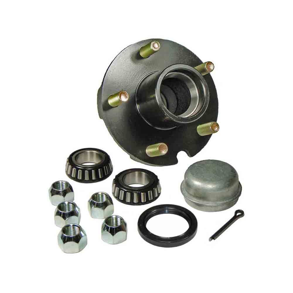
Wheel bearing kits components:
Bearing 1
Nut 1
Sealing/Protective Cap 1
O.E.:
3748.76
3748.79
Ref.:
F-AG:
FEBI BILSTEIN: 31185
OPTIMAL: 657151
S-KF: VKBA 3659
SNR: R166.32
Application:
For CITROEN C3 I (FC_) (2002/02 – /)
For CITROEN C3 Pluriel (HB_) (2003/05 – /)
For CITROEN C2 (JM_) (2003/09 – /)
For CITROEN C3 II (2009/11 – /)
For CITROEN C2 ENTERPRISE (2009/04 – /)
For PEUGEOT 206 Hatchback (2A/C) (1998/08 – /)
For PEUGEOT 206 CC (2D) (2000/09 – /)
For PEUGEOT 206 SW (2E/K) (2002/07 – /)
For PEUGEOT 1007 (KM_) (2005/04 – /)
For PEUGEOT 206 Saloon (2007/03 – /)
How to extend the bearing’s life?
Don’t allow strong impact, such as hammer striking, transfer roller pressure
Use the accurate installation tool, avoid using cloth kind and short fibers
Lubricate the bearing to avoid rust with high-quality oil
General inspection, such as the surrounding temperature, vibrate, noise inspection
Keep bearing cleaning from dirt, dust, pollutant, and moisture.
The bearing should not be ultra cooled.
Front Wheel Bearing Hub Assembly Replacement, Wheel Bearing & Hub Assembly, Hub Bearing Assembly, front bearing hub replacement, hub and bearing replacement, wheel hub bearings, front wheel bearing hub assembly, front wheel bearing hub replacement, hub bearing assembly front, wheel hub assembly, bearing assembly, Front Wheel Bearing and Hub Assembly, Front Wheel Drive Hub and Bearing Assembly
Packing and Delivery:
Work shop:
Exhibitions:
FAQ:
Q1.What is your shipping logistic?
Re: DHL, TNT, FedEx express, by air/sea/train.
Q2:What’s the MOQ?
Re: For the wheel hub assembly. The MOQ is always 50 sets. If ordering together with other models, small quantities can be organized. But need more time due to the production schedule.
Q3. What are your goods of packing?
Re: Generally, our goods will be packed in Neutral white or brown boxes for the hub bearing unit. Our brand packing SI & CZPT are offered. If you have any other packing requests, we shall also handle them.
Q4. What is your sample policy?
Re: We can supply the sample if we have ready parts in stock.
Q5. Do you have any certificates?
Re: Yes, we have the certificate of ISO9001:2015.
Q6:Any warranty of your products.
Re: Sure, We are offering a guarantee for 12 months or 40,000-50,000 km for the aftermarket.
Q7: How can I make an inquiry?
Re: You can contact us by email, telephone, WhatsApp, , etc.
Q8: How long can reply inquiry?
Re: Within 24 hours.
Q9: What’s the delivery time?
Re: Ready stock 10-15 days, production for 30 to 45 days.
Q10: How do you maintain our good business relationship?
Re: 1. Keep stable, reliable quality, competitive price to ensure our customer’s benefit;
2. Optimal lead time.
3. Keep customers updated about the new goods.
4. Make customers satisfaction as our main goal.
Q11: Can we visit the company & factory?
Re: Yes, welcome for your visit & business discussion.
| After-sales Service: | Yes |
|---|---|
| Warranty: | Yes |
| Type: | Wheel Hub Bearing |
| Samples: |
US$ 50/Piece
1 Piece(Min.Order) | Order Sample |
|---|
| Customization: |
Available
| Customized Request |
|---|
.shipping-cost-tm .tm-status-off{background: none;padding:0;color: #1470cc}
|
Shipping Cost:
Estimated freight per unit. |
about shipping cost and estimated delivery time. |
|---|
| Payment Method: |
|
|---|---|
|
Initial Payment Full Payment |
| Currency: | US$ |
|---|
| Return&refunds: | You can apply for a refund up to 30 days after receipt of the products. |
|---|
Are there differences between front and rear axle hubs in terms of design and function?
Yes, there are differences between front and rear axle hubs in terms of design and function. Here’s a detailed explanation of these differences:
1. Design:
The design of front and rear axle hubs can vary based on the specific requirements of each axle position.
Front Axle Hubs: Front axle hubs are typically more complex in design compared to rear axle hubs. This is because front axle hubs are often responsible for connecting the wheels to the steering system and accommodating the front-wheel drive components. Front axle hubs may have provisions for attaching CV (constant velocity) joints, which are necessary for transmitting power from the engine to the front wheels in front-wheel drive or all-wheel drive vehicles. The design of front axle hubs may also incorporate features for connecting the brake rotor, allowing for the integration of the braking system.
Rear Axle Hubs: Rear axle hubs generally have a simpler design compared to front axle hubs. They are primarily responsible for connecting the wheels to the rear axle shafts and supporting the wheel bearings. Rear axle hubs may not require the same level of complexity as front axle hubs since they do not need to accommodate steering components or transmit power from the engine. However, rear axle hubs still play a critical role in supporting the weight of the vehicle, transmitting driving forces, and integrating with the brake system.
2. Function:
The function of front and rear axle hubs differs based on the specific demands placed on each axle position.
Front Axle Hubs: Front axle hubs have the following primary functions:
- Connect the wheel to the steering system, allowing for controlled steering and maneuverability.
- Support the wheel bearings to facilitate smooth wheel rotation and weight distribution.
- Integrate with the front-wheel drive components, such as CV joints, to transmit power from the engine to the front wheels.
- Provide a mounting point for the brake rotor or drum, allowing for the integration of the braking system.
Rear Axle Hubs: Rear axle hubs have the following primary functions:
- Connect the wheel to the rear axle shaft, facilitating power transmission and driving forces.
- Support the wheel bearings to enable smooth wheel rotation and weight distribution.
- Integrate with the brake system, providing a mounting point for the brake rotor or drum for braking performance.
3. Load Distribution:
Front and rear axle hubs also differ in terms of load distribution.
Front Axle Hubs: Front axle hubs bear the weight of the engine, transmission, and other front-end components. They also handle a significant portion of the vehicle’s braking forces during deceleration. As a result, front axle hubs need to be designed to handle higher loads and provide sufficient strength and durability.
Rear Axle Hubs: Rear axle hubs primarily bear the weight of the vehicle’s rear end and support the differential and rear axle shafts. The braking forces on the rear axle hubs are typically lower compared to the front axle hubs. However, they still need to be robust enough to handle the forces generated during acceleration, deceleration, and cornering.
In summary, there are differences between front and rear axle hubs in terms of design and function. Front axle hubs are typically more complex and accommodate steering components and front-wheel drive systems, while rear axle hubs have a simpler design focused on supporting the rear axle and integrating with the brake system. Understanding these differences is important for proper maintenance and repair of the axle hubs in a vehicle.
Are there specific tools required for DIY axle hub replacement, and where can I find them?
When undertaking a DIY axle hub replacement, certain tools are needed to ensure a smooth and successful process. Here are some specific tools that are commonly required for DIY axle hub replacement and where you can find them:
- Jack and jack stands: These tools are essential for raising the vehicle off the ground and providing a stable support system. You can find jacks and jack stands at automotive supply stores, hardware stores, and online retailers.
- Lug wrench or socket set: A lug wrench or a socket set with the appropriate size socket is necessary to loosen and tighten the lug nuts on the wheel. These tools are commonly available at automotive supply stores, hardware stores, and online retailers.
- Torque wrench: A torque wrench is required to tighten the lug nuts on the wheel and other fasteners to the manufacturer’s recommended torque specifications. Torque wrenches can be found at automotive supply stores, tool stores, and online retailers.
- Pry bar: A pry bar is useful for gently separating the axle hub assembly from the mounting point, especially if it is tightly secured. Pry bars are available at automotive supply stores, hardware stores, and online retailers.
- Hammer: A hammer can be used to tap or lightly strike the axle hub assembly or its components for removal or installation. Hammers are commonly available at hardware stores, tool stores, and online retailers.
- Wheel bearing grease: High-quality wheel bearing grease is necessary for lubricating the axle hub assembly and ensuring smooth operation. Wheel bearing grease can be purchased at automotive supply stores, lubricant suppliers, and online retailers.
- Additional tools: Depending on the specific vehicle and axle hub assembly, you may require additional tools such as a socket set, wrenches, pliers, or specific specialty tools. Consult the vehicle’s service manual or online resources for the specific tools needed for your vehicle model.
To find these tools, you can visit local automotive supply stores, hardware stores, or tool stores in your area. They typically carry a wide range of automotive tools and equipment. Alternatively, you can explore online retailers that specialize in automotive tools and equipment, where you can conveniently browse and purchase the tools you need.
It’s important to ensure that the tools you acquire are of good quality and suitable for the task at hand. Investing in quality tools can make the DIY axle hub replacement process more efficient and help achieve better results. Additionally, always follow the manufacturer’s instructions and safety guidelines when using tools and equipment.
In summary, specific tools are required for DIY axle hub replacement, such as a jack and jack stands, lug wrench or socket set, torque wrench, pry bar, hammer, and wheel bearing grease. These tools can be found at automotive supply stores, hardware stores, tool stores, and online retailers. Acquiring quality tools and following proper safety guidelines will contribute to a successful DIY axle hub replacement.
What are the torque specifications for securing an axle hub to the vehicle?
The torque specifications for securing an axle hub to the vehicle may vary depending on the specific make, model, and year of the vehicle. It is crucial to consult the manufacturer’s service manual or appropriate technical resources for the accurate torque specifications for your particular vehicle. Here’s a detailed explanation:
- Manufacturer’s Service Manual: The manufacturer’s service manual is the most reliable and authoritative source for torque specifications. It provides detailed information specific to your vehicle, including the recommended torque values for various components, such as the axle hub. The service manual may specify different torque values for different vehicle models or configurations. You can usually obtain the manufacturer’s service manual from the vehicle manufacturer’s official website or through authorized dealerships.
- Technical Resources: In addition to the manufacturer’s service manual, there are other technical resources available that provide torque specifications. These resources may include specialized automotive repair guides, online databases, or torque specification charts. Reputable automotive websites, professional repair manuals, or automotive forums dedicated to your vehicle’s make or model can be valuable sources for finding accurate torque specifications.
- Online Databases: Some websites offer online databases or torque specification tools that allow you to search for specific torque values based on your vehicle’s make, model, and year. These databases compile torque specifications from various sources and provide a convenient way to access the required information. However, it’s important to verify the accuracy and reliability of the source before relying on the provided torque values.
- Manufacturer Recommendations: In certain cases, the manufacturer may provide torque specifications on the packaging or documentation that accompanies the replacement axle hub. If you are using an OEM (Original Equipment Manufacturer) or aftermarket axle hub, it is advisable to check any provided documentation for torque recommendations specific to that particular product.
Regardless of the source you use to obtain torque specifications, it is essential to follow the recommended values precisely. Torque specifications are specified to ensure proper tightening and secure attachment of the axle hub to the vehicle. Over-tightening or under-tightening can lead to issues such as damage to components, improper seating, or premature wear. It is recommended to use a reliable torque wrench to achieve the specified torque values accurately.
In summary, the torque specifications for securing an axle hub to the vehicle depend on the specific make, model, and year of the vehicle. The manufacturer’s service manual, technical resources, online databases, and manufacturer recommendations are valuable sources to obtain accurate torque specifications. It is crucial to follow the recommended torque values precisely to ensure proper installation and avoid potential issues.
editor by CX 2023-10-30
China Good quality CZPT CZPT Truck Spare Parts Rear Wheel Hub Roller Bearing Wg9231030222 30222 for Truck Axle Parts wholesaler
Product Description
CZPT CZPT truck spare parts rear wheel hub roller bearing WG for truck axle parts
Product Parameters
| Number | WG |
| Name |
Roller Bearing |
| Specification |
Standard |
| Place of origin |
HangZhou China |
| Packing |
As your request |
| Delivery Port |
Any Port |
| Payment Terms |
L/C,T/T,Western Union, Paypal and others |
| Delivery Time |
In 7-15 days |
Detailed Photos
Packaging & Shipping
Our Advantages
HangZhou Sero Import&Export Co.,Ltd. is located in HangZhou city which is a comprehensive trading company that manages all heavy duty truck and light truck auto parts.
We are the authorized dealer of CZPT , deal all series of CZPT models (HOWO,A7,T5G,T7H,70 mining dump truck and etc.) , also engaged in SHACMAN,FOTON,FAW,XIHU (WEST LAKE) DIS.,XIHU (WEST LAKE) DIS.FENG,JAC,XIHU (WEST LAKE) DIS.N heavy duty and light trucks , we provide original and after the market and quality OEM parts .
Our products have been exported to various countries in the world with high quality and competitive price and are well recognized both domestic and abroad.We sincerely promises to all customers and partners to provide excellent products, work together for common development.
Struggle, integrity, thanksgiving, quality is our constant pursuit.
FAQ
1. Q: Are you a manufacturer or trading company?A: We are manufacturer.
2. Q: What about your products quality? A:”Quality is priority. ” We always attach great importance to quality controlling from the very beginning.
3.Q:What payment do you accept? A: T/T, L/C, Trade assurance;
What Are Worm Gears and Worm Shafts?
If you’re looking for a fishing reel with a worm gear system, you’ve probably come across the term ‘worm gear’. But what are worm gears and worm shafts? And what are the advantages and disadvantages of worm gears? Let’s take a closer look! Read on to learn more about worm gears and shafts! Then you’ll be well on your way to purchasing a reel with a worm gear system.
worm gear reducers
Worm shaft reducers have a number of advantages over conventional gear reduction mechanisms. First, they’re highly efficient. While single stage worm reducers have a maximum reduction ratio of about 5 to 60, hypoid gears can typically go up to a maximum of 1 hundred and 20 times. A worm shaft reducer is only as efficient as the gearing it utilizes. This article will discuss some of the advantages of using a hypoid gear set, and how it can benefit your business.
To assemble a worm shaft reducer, first remove the flange from the motor. Then, remove the output bearing carrier and output gear assembly. Lastly, install the intermediate worm assembly through the bore opposite to the attachment housing. Once installed, you should carefully remove the bearing carrier and the gear assembly from the motor. Don’t forget to remove the oil seal from the housing and motor flange. During this process, you must use a small hammer to tap around the face of the plug near the outside diameter of the housing.
Worm gears are often used in reversing prevention systems. The backlash of a worm gear can increase with wear. However, a duplex worm gear was designed to address this problem. This type of gear requires a smaller backlash but is still highly precise. It uses different leads for the opposing tooth face, which continuously alters its tooth thickness. Worm gears can also be adjusted axially.
worm gears
There are a couple of different types of lubricants that are used in worm gears. The first, polyalkylene glycols, are used in cases where high temperature is not a concern. This type of lubricant does not contain any waxes, which makes it an excellent choice in low-temperature applications. However, these lubricants are not compatible with mineral oils or some types of paints and seals. Worm gears typically feature a steel worm and a brass wheel. The brass wheel is much easier to remodel than steel and is generally modeled as a sacrificial component.
The worm gear is most effective when it is used in small and compact applications. Worm gears can greatly increase torque or reduce speed, and they are often used where space is an issue. Worm gears are among the smoothest and quietest gear systems on the market, and their meshing effectiveness is excellent. However, the worm gear requires high-quality manufacturing to perform at its highest levels. If you’re considering a worm gear for a project, it’s important to make sure that you find a manufacturer with a long and high quality reputation.
The pitch diameters of both worm and pinion gears must match. The 2 worm cylinders in a worm wheel have the same pitch diameter. The worm wheel shaft has 2 pitch cylinders and 2 threads. They are similar in pitch diameter, but have different advancing angles. A self-locking worm gear, also known as a wormwheel, is usually self-locking. Moreover, self-locking worm gears are easy to install.
worm shafts
The deflection of worm shafts varies with toothing parameters. In addition to toothing length, worm gear size and pressure angle, worm gear size and number of helical threads are all influencing factors. These variations are modeled in the standard ISO/TS 14521 reference gear. This table shows the variations in each parameter. The ID indicates the worm shaft’s center distance. In addition, a new calculation method is presented for determining the equivalent bending diameter of the worm.
The deflection of worm shafts is investigated using a four-stage process. First, the finite element method is used to compute the deflection of a worm shaft. Then, the worm shaft is experimentally tested, comparing the results with the corresponding simulations. The final stage of the simulation is to consider the toothing geometry of 15 different worm gear toothings. The results of this step confirm the modeled results.
The lead on the right and left tooth surfaces of worms is the same. However, the lead can be varied along the worm shaft. This is called dual lead worm gear, and is used to eliminate play in the main worm gear of hobbing machines. The pitch diameters of worm modules are equal. The same principle applies to their pitch diameters. Generally, the lead angle increases as the number of threads decreases. Hence, the larger the lead angle, the less self-locking it becomes.
worm gears in fishing reels
Fishing reels usually include worm shafts as a part of the construction. Worm shafts in fishing reels allow for uniform worm winding. The worm shaft is attached to a bearing on the rear wall of the reel unit through a hole. The worm shaft’s front end is supported by a concave hole in the front of the reel unit. A conventional fishing reel may also have a worm shaft attached to the sidewall.
The gear support portion 29 supports the rear end of the pinion gear 12. It is a thick rib that protrudes from the lid portion 2 b. It is mounted on a bushing 14 b, which has a through hole through which the worm shaft 20 passes. This worm gear supports the worm. There are 2 types of worm gears available for fishing reels. The 2 types of worm gears may have different number of teeth or they may be the same.
Typical worm shafts are made of stainless steel. Stainless steel worm shafts are especially corrosion-resistant and durable. Worm shafts are used on spinning reels, spin-casting reels, and in many electrical tools. A worm shaft can be reversible, but it is not entirely reliable. There are numerous benefits of worm shafts in fishing reels. These fishing reels also feature a line winder or level winder.
worm gears in electrical tools
Worms have different tooth shapes that can help increase the load carrying capacity of a worm gear. Different tooth shapes can be used with circular or secondary curve cross sections. The pitch point of the cross section is the boundary for this type of mesh. The mesh can be either positive or negative depending on the desired torque. Worm teeth can also be inspected by measuring them over pins. In many cases, the lead thickness of a worm can be adjusted using a gear tooth caliper.
The worm shaft is fixed to the lower case section 8 via a rubber bush 13. The worm wheel 3 is attached to the joint shaft 12. The worm 2 is coaxially attached to the shaft end section 12a. This joint shaft connects to a swing arm and rotates the worm wheel 3.
The backlash of a worm gear may be increased if the worm is not mounted properly. To fix the problem, manufacturers have developed duplex worm gears, which are suitable for small backlash applications. Duplex worm gears utilize different leads on each tooth face for continuous change in tooth thickness. In this way, the center distance of the worm gear can be adjusted without changing the worm’s design.
worm gears in engines
Using worm shafts in engines has a few benefits. First of all, worm gears are quiet. The gear and worm face move in opposite directions so the energy transferred is linear. Worm gears are popular in applications where torque is important, such as elevators and lifts. Worm gears also have the advantage of being made from soft materials, making them easy to lubricate and to use in applications where noise is a concern.
Lubricants are necessary for worm gears. The viscosity of lubricants determines whether the worm is able to touch the gear or wheel. Common lubricants are ISO 680 and 460, but higher viscosity oil is not uncommon. It is essential to use the right lubricants for worm gears, since they cannot be lubricated indefinitely.
Worm gears are not recommended for engines due to their limited performance. The worm gear’s spiral motion causes a significant reduction in space, but this requires a high amount of lubrication. Worm gears are susceptible to breaking down because of the stress placed on them. Moreover, their limited speed can cause significant damage to the gearbox, so careful maintenance is essential. To make sure worm gears remain in top condition, you should inspect and clean them regularly.
Methods for manufacturing worm shafts
A novel approach to manufacturing worm shafts and gearboxes is provided by the methods of the present invention. Aspects of the technique involve manufacturing the worm shaft from a common worm shaft blank having a defined outer diameter and axial pitch. The worm shaft blank is then adapted to the desired gear ratio, resulting in a gearbox family with multiple gear ratios. The preferred method for manufacturing worm shafts and gearboxes is outlined below.
A worm shaft assembly process may involve establishing an axial pitch for a given frame size and reduction ratio. A single worm shaft blank typically has an outer diameter of 100 millimeters, which is the measurement of the worm gear set’s center distance. Upon completion of the assembly process, the worm shaft has the desired axial pitch. Methods for manufacturing worm shafts include the following:
For the design of the worm gear, a high degree of conformity is required. Worm gears are classified as a screw pair in the lower pairs. Worm gears have high relative sliding, which is advantageous when comparing them to other types of gears. Worm gears require good surface finish and rigid positioning. Worm gear lubrication usually comprises surface active additives such as silica or phosphor-bronze. Worm gear lubricants are often mixed. The lubricant film that forms on the gear teeth has little impact on wear and is generally a good lubricant.
China Good quality Wholesale Axle Bearing Automobile Parts Dac356535 near me factory
Product Description
Welcome to choose KORTON INDUSTRIAL LIMITED.
NO 1. our adwantages:
1. 14 years bearing products manufacturing and exporting experiences.
2. OEM order and non-standard bearing order can be accepted.
3. Many sizes of bearing are available. Large quantity bearing can be provided.
4. To respect customers, you can choose the loading port.
5. A certain number of free sample can be provide to support our customer’s after-sale services and warranty.
NO 2. Description: Auto wheel bearing:
The main functions of wheel hub bearings are load and provide accurate guidance to the turn of hub bearings. Hub bearings not only carry axial load but also carry radial load, they are important components. They can carry heavy radial load which include axial and radial load and torques load, they can limit axial displacement both sides. They are mainly used in components which limitation of bearings and shell axial displacement of both sides. Hub bearings’ design are familiar to the 2 back to back order single row conntact ball bearings, but the width are shorter than single row bearings. Compare to the single row bearings hub bearings have better rigidity.
NO 3. OEM all brand bearing
NO 4. Auto Wheel Bearing Specification:
| Seals Types | ZZ,2RS,OPEN | ||||||||
| Vibration Level | Z1V1,Z2V2,Z3V3 | ||||||||
| Clearance | C2,C0,C3,C4,C5 | ||||||||
| Tolerance Codes | ABEC-1,ABEC-3,ABEC-5 | ||||||||
| Materral | GCr15-China/AISI521W | ||||||||
| DAC30600037 | 30 | 60 | 37 | 37 | 0.42 | 529891AB | BA2B633313C | DAC3060W | |
| DAC30620038 | 30 | 62 | 38 | 38 | 0.52 | 545312 | 418780 | 30BWD10 | |
| DAC30630042 | 30 | 63 | 42 | 42 | 0.57 | 581736 | 45716A | 30BWD01A | |
| DAC30640042 | 30 | 64 | 42 | 42 | 0.5 | 34BWD03ACA78 | DAC3064W2R | ||
| DAC32720045 | 32 | 72 | 45 | 45 | 0.81 | 531910 | 32BWD05CA75 | ||
| DAC34620037 | 34 | 62 | 37 | 37 | 0.41 | 561447 | BAHB311316B | 34BWD08/CA70 | |
| DAC34640037 | 34 | 64 | 37 | 37 | 0.43 | 540466B | 3 0571 6DA | 34BWD11 | DAC3464G1 |
| DAC34660037 | 34 | 66 | 37 | 37 | 0.5 | 580400CA | 636114A | 34BWD10B | |
| DAC34670037 | 34 | 67 | 37 | 37 | 0.52 | 532066DB | |||
| DAC34680037 | 34 | 68 | 37 | 37 | 0.55 | 567918B | DAC3468DW | ||
| DAC35620040 | 35 | 62 | 40 | 40 | 0.43 | 430042C | |||
| DAC35640037 | 35 | 64 | 37 | 37 | 0.41 | BT2B445620B | |||
| DAC35650035 | 35 | 65 | 35 | 35 | 0.4 | 546238A | 443952 | DAC3565WCS30 | |
| DAC35660033 | 35 | 66 | 33 | 33 | 0.43 | BAHB633676 | |||
| DAC35660037 | 35 | 66 | 37 | 37 | 0.48 | 544307 | BAHB311309 | DAC35660037 | |
| DAC35680033/30 | 35 | 68 | 33 | 30 | 0.47 | 546238 | BA2B445535AE | 35BWD07A | DAC3568W-6 |
| DAC35680037 | 35 | 68 | 37 | 37 | 0.52 | 541153 | 633295 | DAC3568A2RS | |
| DAC35720033 | 35 | 72 | 33 | 33 | 0.58 | 548083 | BA2B446762B | ||
| DAC35725713/31 | 35 | 72 | 33 | 31 | 0.56 | 562686 | FWB14 | 35BWD06ACA111 | DAC357233B-1W |
| DAC3572571 | 35 | 72 | 33 | 33 | 0.58 | 548083 | BAHB633669 | 35BWD08A | DAC357545CW2R |
| DAC35720034 | 35 | 72 | 34 | 34 | 0.58 | 54 0571 | BAHB633967 | 35BWD01 | DAC357234A |
| DAC3572571 | 35 | 72 | 34 | 34 | 0.58 | BAHB633528F | |||
| DAC36640042 | 36 | 64 | 42 | 42 | 0.46 | CRI-0787 | |||
| DAC36680033 | 36 | 68 | 33 | 33 | 0.47 | DAC3668AWCS36 | |||
| DAC37720033 | 37 | 72 | 33 | 33 | 0.5 | BAH-0051B |
NO 6. Some Auto wheel bearing OEM number and Application:
| OEM NUMBERS | DESCRIPTION | APPLICATION |
| B001-33-043 | WHEEL BEARINGS | SPORTAGE |
| 04495-0K120 | WHEEL BEARINGS | HILUX’07 |
| 42409-19015 | WHEEL BEARING REAR | COROLLA |
| 42409-33571 | WHEEL BEARING REAR | CAMRY 1 |
| 90369-38011 | WHEEL BEARING FRONT | COROLLA 3872 |
| 43504-12090 | WHEEL HUB FRONT | COROLLA |
| 42409-2571 | WHEEL BEARING REAR | AVENSIS, CARINA |
| 43502-20131 | WHEEL HUB FRONT | CARINA |
| 44300-S3V-AO1 | WHEEL BEARINGS FRONT | TRUCK / LAND CRUISE |
| 42409-42571 | WHEEL BEARINGS REAR | RAV 4 |
| 518506 | WHEEL HUB FRONT | CAMRY |
| 175407615 | WHEEL HUB FRONT | GOLF 1 |
| 331598625 | WHEEL BEARING REAR | GOLF II |
| 3871 | WHEEL BEARING FRONT | TOY STARLET |
| 4382 | WHEEL BEARING | CAMRY |
| 90368-50008 | WHEEL BEARING | DYNA |
| 90369-32003 | WHEEL BEARING | RX80 FRONT |
| 45710-C6000 | WHEEL BEARING | NISSAN PATROL FRONT |
| 45710-50Y00-D | WHEEL BEARING | NISSAN SUNNY |
| 45710-71L00-D | WHEEL BEARING | NISSAN |
| 42200-SH3-970-D | WHEEL BEARING | HONDA CIVIC |
| 42300-SD4-004 | WHEEL BEARING | HONDA BALLADE |
| 43210-C9300-D | WHEEL BEARING | NISSAN PATROL |
| 43210-D5710-D | WHEEL BEARING | NISS-B/BIRD REAR |
| 44200-SM4-0131 | WHEEL BEARING | HONDA-CIVIC |
| 44300-SB2-965 | WHEEL BEARING | HONDA |
| 44300-S04-0040 | WHEEL BEARING | HONDA-CIVIC |
| MB584761 | WHEEL BEARING | MITS-LANCER |
| MB664447 | WHEEL BEARING | MITS-PAJERO |
| 46T080604 | WHEEL BEARING | COROLLA-REAR |
| DG4 0571 6WRS/DG4094W | WHEEL BEARING REAR | HIACE 4X4 |
| 3874 | WHEEL BEARINGS | CORONA |
| 157148/10 | WHEEL BEARINGS | L/CRUISER |
| 104948/10 | WHEEL BEARINGS | L/CRUISER |
| 48548/10 | WHEEL BEARINGS | HIACE 2Y |
| 12649/10 | WHEEL BEARINGS | HIACE 2Y |
| 30303D | WHEEL BEARINGS | L/CRUISER |
| 4T-CR1-0881 | WHEEL BEARINGS | BLUEBIRD |
| 11162/ | WHEEL BEARINGS | LAND ROVER |
| 69345/10 | WHEEL BEARINGS | MAZDA 323 |
| 11749/10 | WHEEL BEARINGS | NISSAN 1400 |
| 35715 | WHEEL BEARINGS | MAZDA B1800 |
| 35714 | WHEEL BEARINGS | L/CRUISER |
| 67048/10 | WHEEL BEARINGS | CRESSIDA |
| 44649/10 | WHEEL BEARINGS | NISSAN 1400 |
| 45449/10 | WHEEL BEARINGS | COROLLA DX |
| 30849/10 | WHEEL BEARINGS | TOYOTA |
| 6308 | WHEEL BEARINGS | TOY HIACE |
| U399 | WHEEL BEARINGS | TOY HILUX |
| 11949/10 | WHEEL BEARINGS | NISSAN 1400 |
| 30304 | WHEEL BEARINGS | L/CRUISER |
| 4080 | WHEEL BEARINGS | MITSUBISHI |
| 603049/10 | WHEEL BEARINGS | TOYOTA |
| 6306CNXL330 | GEAR BOX BEARINGS | NISSAN TD27 |
| TR080702J | GEAR BOX BEARINGS | TOYOTA COROLLA |
| 3314598 | WHEEL BEARINGS | FORD RANGER |
| DAC38640036 | WHEEL BEARINGS | TOYOTA COROLLA REAR |
| TR070904-J-N | DIFF BEARINGS | L/CRUISER |
| R30-13 | DIFF BEARINGS | L/CRUISER |
| TR100802-I-N | DIFF BEARINGS | L/CRUISER |
| 42BWD06 | WHEEL BEARINGS | NISSAN BLUEBIRD |
| 46T 0571 05 | WHEEL BEARINGS | TOYOTA LUCIDA |
| HM801310-22-N | DIFF BEARINGS | MITSUBISHI CANTER |
| LM603049/10 | WHEEL BEARINGS | FORD/L/ROVER |
| 17831/17887 | DIFF BEARINGS | TOYOTA HIACE |
| 2788 | WHEEL BEARINGS | L/CRUISER |
| 26882 | WHEEL BEARINGS | L/CRUISER |
| 28985/28920 | DIFF BEARINGS | MITSUBISHI CANTER |
| HM801349-N | DIFF BEARINGS | MITSUBISHI CANTER |
| 50KW8019 | DIFF BEARINGS | MITSUBISHI CANTER |
| 45289 | WHEEL BEARINGS | TOYOTA DYNA |
| 43BWD03 | WHEEL BEARINGS | TOYOTA MARK11 |
| 35BWD16 | WHEEL BEARINGS | NISSAN MARCH |
| LM300811 | WHEEL BEARINGS | NISSAN 1TONNER |
| LM60571 | WHEEL BEARINGS | NISSAN 1TONNER |
| 35712 | WHEEL BEARINGS | MITSUBISHI CANTER FRONT |
| 35718j/57307 | WHEEL BEARINGS | MITSUBISHI L200 REAR |
| ST2749 | WHEEL BEARINGS | TOYOTA STARLET FRONT |
| 55KW02 | WHEEL BEARINGS | MITSUBISHI FUSO FRONT |
| 55KW01 | WHEEL BEARINGS | MITSUBISHI FUSO FRONT |
| 25KC802 | DIFF BEARINGS | L/CRUISER |
| 35BW08 | WHEEL BEARINGS | TOWNACE REAR |
| 32207 | WHEEL BEARINGS | MITSUBISHI CANTER FRONT |
| DAC4380A | WHEEL BEARINGS | MAZDA 626 |
| 46T 0571 04A | WHEEL BEARINGS | TOYOTA CONDOR FRONT |
| TR0708030 | DIFF BEARINGS | TOYOTA HIACE |
| 32012X | WHEEL BEARINGS | MITSUBISHI L200/CANTER REAR |
| 4276 | WHEEL BEARINGS | MITSUBISHI L200/CANTER REAR |
| 28580 | DIFF BEARINGS | TOYOTA COASTER |
| 3579R/25 | WHEEL BEARINGS | TOYOTA DYNA FRONT |
| HR32210J | DIFF BEARINGS | MITSUBISHI CANTER |
| HR32206J | WHEEL BEARINGS | NISSAN SUNNY |
| HR35717J | DIFF BEARINGS | NISSAN |
| DU5496-5 | WHEEL BEARINGS | TOYOTA HILUX |
| 40KW019 | WHEEL BEARINGS | MITSUBISHI FUSO FRONT |
| TR0607R | DIFF BEARINGS | TOYOTA HIACE |
| TR57326 | DIFF BEARINGS | TOYOTA COASTER |
| 2474 | DIFF BEARINGS | TOYOTA COASTER |
| 33013A | WHEEL BEARINGS | TOYOTA COASTER |
| HR32307CN | DIFF BEARINGS | TOYOTA HILUX |
| 32310 | WHEEL BEARINGS | ISUZU LIGHT TRUCK |
| 40BWD12 | WHEEL BEARINGS | TOYOTA VISTA |
| 33205JR | WHEEL BEARINGS | TOYOTA VISTA |
| LM300849 | WHEEL BEARINGS | NISSAN-DATSUN |
| 50KWH01 | WHEEL BEARINGS | MITSUBISHI SPORTERO |
| 40KW01 | DIFF BEARINGS | MITSUBISHI FUSO |
| 30305 | WHEEL BEARINGS | NISSAN |
| 32571XJ | WHEEL BEARINGS | NISSAN |
| 35718 | WHEEL BEARINGS | NISSAN |
| 32304 | WHEEL BEARINGS | ISUZU |
| DAC43792RS | WHEEL BEARINGS | HONDA CRV |
| 40KWD02 | WHEEL BEARINGS | MITSUBISHI SPORTERO |
| 38BWD06 | WHEEL BEARINGS | TOYOTA MARK11 FRONT |
| 43KWD04 | WHEEL BEARINGS | NISSAN PRIMERA |
| 427638 | WHEEL BEARINGS | TOYOTA REGUS FRONT |
| LM68149/10 | WHEEL BEARINGS | CROWN FRONT |
| LM12749/10 | WHEEL BEARINGS | CROWN FRONT |
| 32005JR | WHEEL BEARINGS | MAZDA FRONT |
| 35BCD08 | WHEEL BEARINGS | TOYOTA NOAH REAR |
| LM506810 | WHEEL BEARINGS | L/CRUISER |
| ET33011 | WHEEL BEARINGS | NISSAN CABSTER |
| RNU0727 | WHEEL BEARINGS | L/CRUISER |
| 46T08805 | WHEEL BEARINGS | MITSUBISHI PAJERO |
| 1220 | WHEEL BEARINGS | TOYOTA DYNA |
| 28584 | WHEEL BEARINGS | TOYOTA COASTER |
| 469-N | WHEEL BEARINGS | TOYOTA COASTER REAR |
| 28BWD01A | WHEEL BEARINGS | TOYOTA COROLLA REAR |
| 57305 | WHEEL BEARINGS | TOYOTA TOWNACE |
| 40BWD06 | WHEEL BEARINGS | MAZDA FRONT |
| AU 0571 -2 | WHEEL BEARINGS | NISSAN X-TRAIL |
| ME6 0571 4 | THRUST BEARING | MITS-4D30 |
| 30502-28E20 | THRUST BEARING | TD27 |
| 30502-53J00 | THRUST BEARING | GA16 |
| 31230-12140 | THRUST BEARING | EE90 |
| 31230-35070 | THRUST BEARING | TOY-3L |
| 31250-35050 | THRUST BEARING | TOY-2L |
| 31230-35090 | THRUST BEARING | TOY-5L |
| 31230-36160 | THRUST BEARING | TOY-1HZ |
| 31230-60130 | THRUST BEARING | TOY-1FZ |
| MD703270 | THRUST BEARING | MITS-4D55 |
| ME657110-D | THRUST BEARING | MITS-CANTER |
| 5712-16-222-D | THRUST BEARING | MAZ-HA |
| 31230-60120 | THRUST BEARING | TOY-2H |
| 31230-60150 | THRUST BEARING | TOY-FJ80 |
| 31230-32571 | THRUST BEARING | TOY-3S |
| 1304-16-510B | THRUST BEARING | MAZ-TITAN |
| MD719469-D | THRUST BEARING | MITS-4D56 |
| 31230-36150 | THRUST BEARING | COASTER |
| 31230-32060 | THRUST BEARING | TOY-4AF |
| 58SCRN37P | THRUST BEARINGS | TOYOTA 1KZ |
Our factory:
Our Products:
Why Choose Us:
We are an industrial company.We have our own brand: SFNB .If you interested in our product,I can take you to visit our factory.
Our factory have advanced testing equipment,before the every product leave the factory,we will be testing.We can send samples to you,you can test the quality,and if you accept the sample quality,we can promise: the follow-up orders’ quality will be the same as samples.
About ordinary standard type of bearing ,We have rich inventory,not have MOQ,if your need a product is Non-standard size,need customize,we will according the product size to determine the MOQ.
Our company can accept OEM,you can send sample to me,we can manufacturing products the same as sample.Meanwhile,we also can accept some well-known brands of OEM,
If the amount of money is less,you can pay it by Paypal or Alipay.Of course you can payment by TT or Western Union etc.
The Four Basic Components of a Screw Shaft
There are 4 basic components of a screw shaft: the Head, the Thread angle, and the Threaded shank. These components determine the length, shape, and quality of a screw. Understanding how these components work together can make purchasing screws easier. This article will cover these important factors and more. Once you know these, you can select the right type of screw for your project. If you need help choosing the correct type of screw, contact a qualified screw dealer.
Thread angle
The angle of a thread on a screw shaft is the difference between the 2 sides of the thread. Threads that are unified have a 60 degree angle. Screws have 2 parts: a major diameter, also known as the screw’s outside diameter, and a minor diameter, or the screw’s root diameter. A screw or nut has a major diameter and a minor diameter. Each has its own angle, but they all have 1 thing in common – the angle of thread is measured perpendicularly to the screw’s axis.
The pitch of a screw depends on the helix angle of the thread. In a single-start screw, the lead is equal to the pitch, and the thread angle of a multiple-start screw is based on the number of starts. Alternatively, you can use a square-threaded screw. Its square thread minimizes the contact surface between the nut and the screw, which improves efficiency and performance. A square thread requires fewer motors to transfer the same load, making it a good choice for heavy-duty applications.
A screw thread has 4 components. First, there is the pitch. This is the distance between the top and bottom surface of a nut. This is the distance the thread travels in a full revolution of the screw. Next, there is the pitch surface, which is the imaginary cylinder formed by the average of the crest and root height of each tooth. Next, there is the pitch angle, which is the angle between the pitch surface and the gear axis.
Head
There are 3 types of head for screws: flat, round, and hexagonal. They are used in industrial applications and have a flat outer face and a conical interior. Some varieties have a tamper-resistant pin in the head. These are usually used in the fabrication of bicycle parts. Some are lightweight, and can be easily carried from 1 place to another. This article will explain what each type of head is used for, and how to choose the right 1 for your screw.
The major diameter is the largest diameter of the thread. This is the distance between the crest and the root of the thread. The minor diameter is the smaller diameter and is the distance between the major and minor diameters. The minor diameter is half the major diameter. The major diameter is the upper surface of the thread. The minor diameter corresponds to the lower extreme of the thread. The thread angle is proportional to the distance between the major and minor diameters.
Lead screws are a more affordable option. They are easier to manufacture and less expensive than ball screws. They are also more efficient in vertical applications and low-speed operations. Some types of lead screws are also self-locking, and have a high coefficient of friction. Lead screws also have fewer parts. These types of screw shafts are available in various sizes and shapes. If you’re wondering which type of head of screw shaft to buy, this article is for you.
Threaded shank
Wood screws are made up of 2 parts: the head and the shank. The shank is not threaded all the way up. It is only partially threaded and contains the drive. This makes them less likely to overheat. Heads on wood screws include Oval, Round, Hex, Modified Truss, and Flat. Some of these are considered the “top” of the screw.
Screws come in many sizes and thread pitches. An M8 screw has a 1.25-mm thread pitch. The pitch indicates the distance between 2 identical threads. A pitch of 1 is greater than the other. The other is smaller and coarse. In most cases, the pitch of a screw is indicated by the letter M followed by the diameter in millimetres. Unless otherwise stated, the pitch of a screw is greater than its diameter.
Generally, the shank diameter is smaller than the head diameter. A nut with a drilled shank is commonly used. Moreover, a cotter pin nut is similar to a castle nut. Internal threads are usually created using a special tap for very hard metals. This tap must be followed by a regular tap. Slotted machine screws are usually sold packaged with nuts. Lastly, studs are often used in automotive and machine applications.
In general, screws with a metric thread are more difficult to install and remove. Fortunately, there are many different types of screw threads, which make replacing screws a breeze. In addition to these different sizes, many of these screws have safety wire holes to keep them from falling. These are just some of the differences between threaded screw and non-threaded. There are many different types of screw threads, and choosing the right 1 will depend on your needs and your budget.
Point
There are 3 types of screw heads with points: cone, oval, and half-dog. Each point is designed for a particular application, which determines its shape and tip. For screw applications, cone, oval, and half-dog points are common. Full dog points are not common, and they are available in a limited number of sizes and lengths. According to ASTM standards, point penetration contributes as much as 15% of the total holding power of the screw, but a cone-shaped point may be more preferred in some circumstances.
There are several types of set screws, each with its own advantage. Flat-head screws reduce indentation and frequent adjustment. Dog-point screws help maintain a secure grip by securing the collar to the screw shaft. Cup-point set screws, on the other hand, provide a slip-resistant connection. The diameter of a cup-point screw is usually half of its shaft diameter. If the screw is too small, it may slack and cause the screw collar to slip.
The UNF series has a larger area for tensile stress than coarse threads and is less prone to stripping. It’s used for external threads, limited engagement, and thinner walls. When using a UNF, always use a standard tap before a specialized tap. For example, a screw with a UNF point is the same size as a type C screw but with a shorter length.
Spacer
A spacer is an insulating material that sits between 2 parts and centers the shaft of a screw or other fastener. Spacers come in different sizes and shapes. Some of them are made of Teflon, which is thin and has a low coefficient of friction. Other materials used for spacers include steel, which is durable and works well in many applications. Plastic spacers are available in various thicknesses, ranging from 4.6 to 8 mm. They’re suitable for mounting gears and other items that require less contact surface.
These devices are used for precision fastening applications and are essential fastener accessories. They create clearance gaps between the 2 joined surfaces or components and enable the screw or bolt to be torqued correctly. Here’s a quick guide to help you choose the right spacer for the job. There are many different spacers available, and you should never be without one. All you need is a little research and common sense. And once you’re satisfied with your purchase, you can make a more informed decision.
A spacer is a component that allows the components to be spaced appropriately along a screw shaft. This tool is used to keep space between 2 objects, such as the spinning wheel and an adjacent metal structure. It also helps ensure that a competition game piece doesn’t rub against an adjacent metal structure. In addition to its common use, spacers can be used in many different situations. The next time you need a spacer, remember to check that the hole in your screw is threaded.
Nut
A nut is a simple device used to secure a screw shaft. The nut is fixed on each end of the screw shaft and rotates along its length. The nut is rotated by a motor, usually a stepper motor, which uses beam coupling to accommodate misalignments in the high-speed movement of the screw. Nuts are used to secure screw shafts to machined parts, and also to mount bearings on adapter sleeves and withdrawal sleeves.
There are several types of nut for screw shafts. Some have radial anti-backlash properties, which prevent unwanted radial clearances. In addition, they are designed to compensate for thread wear. Several nut styles are available, including anti-backlash radial nuts, which have a spring that pushes down on the nut’s flexible fingers. Axial anti-backlash nuts also provide thread-locking properties.
To install a ball nut, you must first align the tangs of the ball and nut. Then, you must place the adjusting nut on the shaft and tighten it against the spacer and spring washer. Then, you need to lubricate the threads, the ball grooves, and the spring washers. Once you’ve installed the nut, you can now install the ball screw assembly.
A nut for screw shaft can be made with either a ball or a socket. These types differ from hex nuts in that they don’t need end support bearings, and are rigidly mounted at the ends. These screws can also have internal cooling mechanisms to improve rigidity. In this way, they are easier to tension than rotating screws. You can also buy hollow stationary screws for rotator nut assemblies. This type is great for applications requiring high heat and wide temperature changes, but you should be sure to follow the manufacturer’s instructions.
China factory Wg4005415347 HD900094100061 286010 Bth-0074A Front Wheel Bearing for Max Axle Suspension Truck Spare Parts with Good quality
Product Description
Product Description
AUTO bearing for ALL KINDS OF TRUCK,TRACTOR,TRAILER
PART NUMBER:
WG4 617546A 576467 445539AA FC12571S01 25BWD01 27BWD01J 28BWD03A
28BWD01A 30BWD08 IR8040 30BWD01A 30BWD04 GB1571S05 617546A
445539AA DAC2552W-7 BAH5AW
DAC306571RS DAC3060W DAC3063W-1 DAC3064W2RKB
86CL6395F0 DZ911416
86CL6082FO 86CL6082FOC 86CL6089FOD 86NL6089FOA 92CL6093FO
3303
014255713 A
0142508803 014255713
LRS0571 LRS00922 LRS819 LRS922 LRT0 0571 LRT668
Detailed Photos
We have factory to produce all kinds of BEARING for heavy duty truck,light truck,tractor..
We can also produce according to drawing or samples.
Packaging & Shipping
1. Packaging details: carton and wooden box packaging,woven bag,brown box, or
according to customer requirements.
2. Delivery Period: 7-30 working days after
receiving 30% deposit byTT
3. Port: HangZhou Port,China.
4. Transport: By sea, by
air,DHL,FEDEX,UPS,TNT,
FAQ
1.Q:About the payment term.
A: We can accept TT,LC,PAYPAL,WESTERNUION,and so on
2.Q:About the Quality and price
A: We supply good quality products to all our customers,give the competitive price.
3.Q:About the warranty period
A:At least half year, some parts are even longer.
4. Q:How to make order ?
A:Customer can contact us online,or send email with detail inquiry list,then we can reply soon
5.Q:About the discount
A:If the quantity large,we will give resonalbe discount.And for long time cooperation customer,we can give credit support
Analytical Approaches to Estimating Contact Pressures in Spline Couplings
A spline coupling is a type of mechanical connection between 2 rotating shafts. It consists of 2 parts – a coupler and a coupling. Both parts have teeth which engage and transfer loads. However, spline couplings are typically over-dimensioned, which makes them susceptible to fatigue and static behavior. Wear phenomena can also cause the coupling to fail. For this reason, proper spline coupling design is essential for achieving optimum performance.
Modeling a spline coupling
Spline couplings are becoming increasingly popular in the aerospace industry, but they operate in a slightly misaligned state, causing both vibrations and damage to the contact surfaces. To solve this problem, this article offers analytical approaches for estimating the contact pressures in a spline coupling. Specifically, this article compares analytical approaches with pure numerical approaches to demonstrate the benefits of an analytical approach.
To model a spline coupling, first you create the knowledge base for the spline coupling. The knowledge base includes a large number of possible specification values, which are related to each other. If you modify 1 specification, it may lead to a warning for violating another. To make the design valid, you must create a spline coupling model that meets the specified specification values.
After you have modeled the geometry, you must enter the contact pressures of the 2 spline couplings. Then, you need to determine the position of the pitch circle of the spline. In Figure 2, the centre of the male coupling is superposed to that of the female spline. Then, you need to make sure that the alignment meshing distance of the 2 splines is the same.
Once you have the data you need to create a spline coupling model, you can begin by entering the specifications for the interface design. Once you have this data, you need to choose whether to optimize the internal spline or the external spline. You’ll also need to specify the tooth friction coefficient, which is used to determine the stresses in the spline coupling model 20. You should also enter the pilot clearance, which is the clearance between the tip 186 of a tooth 32 on 1 spline and the feature on the mating spline.
After you have entered the desired specifications for the external spline, you can enter the parameters for the internal spline. For example, you can enter the outer diameter limit 154 of the major snap 54 and the minor snap 56 of the internal spline. The values of these parameters are displayed in color-coded boxes on the Spline Inputs and Configuration GUI screen 80. Once the parameters are entered, you’ll be presented with a geometric representation of the spline coupling model 20.
Creating a spline coupling model 20
The spline coupling model 20 is created by a product model software program 10. The software validates the spline coupling model against a knowledge base of configuration-dependent specification constraints and relationships. This report is then input to the ANSYS stress analyzer program. It lists the spline coupling model 20’s geometric configurations and specification values for each feature. The spline coupling model 20 is automatically recreated every time the configuration or performance specifications of the spline coupling model 20 are modified.
The spline coupling model 20 can be configured using the product model software program 10. A user specifies the axial length of the spline stack, which may be zero, or a fixed length. The user also enters a radial mating face 148, if any, and selects a pilot clearance specification value of 14.5 degrees or 30 degrees.
A user can then use the mouse 110 to modify the spline coupling model 20. The spline coupling knowledge base contains a large number of possible specification values and the spline coupling design rule. If the user tries to change a spline coupling model, the model will show a warning about a violation of another specification. In some cases, the modification may invalidate the design.
In the spline coupling model 20, the user enters additional performance requirement specifications. The user chooses the locations where maximum torque is transferred for the internal and external splines 38 and 40. The maximum torque transfer location is determined by the attachment configuration of the hardware to the shafts. Once this is selected, the user can click “Next” to save the model. A preview of the spline coupling model 20 is displayed.
The model 20 is a representation of a spline coupling. The spline specifications are entered in the order and arrangement as specified on the spline coupling model 20 GUI screen. Once the spline coupling specifications are entered, the product model software program 10 will incorporate them into the spline coupling model 20. This is the last step in spline coupling model creation.
Analysing a spline coupling model 20
An analysis of a spline coupling model consists of inputting its configuration and performance specifications. These specifications may be generated from another computer program. The product model software program 10 then uses its internal knowledge base of configuration dependent specification relationships and constraints to create a valid three-dimensional parametric model 20. This model contains information describing the number and types of spline teeth 32, snaps 34, and shoulder 36.
When you are analysing a spline coupling, the software program 10 will include default values for various specifications. The spline coupling model 20 comprises an internal spline 38 and an external spline 40. Each of the splines includes its own set of parameters, such as its depth, width, length, and radii. The external spline 40 will also contain its own set of parameters, such as its orientation.
Upon selecting these parameters, the software program will perform various analyses on the spline coupling model 20. The software program 10 calculates the nominal and maximal tooth bearing stresses and fatigue life of a spline coupling. It will also determine the difference in torsional windup between an internal and an external spline. The output file from the analysis will be a report file containing model configuration and specification data. The output file may also be used by other computer programs for further analysis.
Once these parameters are set, the user enters the design criteria for the spline coupling model 20. In this step, the user specifies the locations of maximum torque transfer for both the external and internal spline 38. The maximum torque transfer location depends on the configuration of the hardware attached to the shafts. The user may enter up to 4 different performance requirement specifications for each spline.
The results of the analysis show that there are 2 phases of spline coupling. The first phase shows a large increase in stress and vibration. The second phase shows a decline in both stress and vibration levels. The third stage shows a constant meshing force between 300N and 320N. This behavior continues for a longer period of time, until the final stage engages with the surface.
Misalignment of a spline coupling
A study aimed to investigate the position of the resultant contact force in a spline coupling engaging teeth under a steady torque and rotating misalignment. The study used numerical methods based on Finite Element Method (FEM) models. It produced numerical results for nominal conditions and parallel offset misalignment. The study considered 2 levels of misalignment – 0.02 mm and 0.08 mm – with different loading levels.
The results showed that the misalignment between the splines and rotors causes a change in the meshing force of the spline-rotor coupling system. Its dynamics is governed by the meshing force of splines. The meshing force of a misaligned spline coupling is related to the rotor-spline coupling system parameters, the transmitting torque, and the dynamic vibration displacement.
Despite the lack of precise measurements, the misalignment of splines is a common problem. This problem is compounded by the fact that splines usually feature backlash. This backlash is the result of the misaligned spline. The authors analyzed several splines, varying pitch diameters, and length/diameter ratios.
A spline coupling is a two-dimensional mechanical system, which has positive backlash. The spline coupling is comprised of a hub and shaft, and has tip-to-root clearances that are larger than the backlash. A form-clearance is sufficient to prevent tip-to-root fillet contact. The torque on the splines is transmitted via friction.
When a spline coupling is misaligned, a torque-biased thrust force is generated. In such a situation, the force can exceed the torque, causing the component to lose its alignment. The two-way transmission of torque and thrust is modeled analytically in the present study. The analytical approach provides solutions that can be integrated into the design process. So, the next time you are faced with a misaligned spline coupling problem, make sure to use an analytical approach!
In this study, the spline coupling is analyzed under nominal conditions without a parallel offset misalignment. The stiffness values obtained are the percentage difference between the nominal pitch diameter and load application diameter. Moreover, the maximum percentage difference in the measured pitch diameter is 1.60% under a torque of 5000 N*m. The other parameter, the pitch angle, is taken into consideration in the calculation.
China best Auto Parts Accessories Front Axle Wheel Hub Bearing Unit Assembly Hub Unit and Bearing Car with Best Sales
Product Description
Products Description
| Standard | ISO/BS/JIS/SGS/ROSH |
| Quality guarantee | 12 months |
| Leading time | 30 days |
| MOQ | 100pcs |
| Advantage | 1.Aftermarket Supplier 2.Factory Price 3.Large Stock |
| Packing |
Neutral carton Custom packaging:Custom Made Box or Logo Extra protective: Pallet ,Wooden Case |
| Our Factory | 5000 m² factory 200 Professional worker 20 Factory lines 5 QC lines Advanced machinery and equipment |
Our advantage
1. High Quality and competitive price, we dare not say our products are the best, but we assure that the quality and the price is reasonable.
2. OEM quality standard, no noise, with long service life.
3. Can develop according customers’ clutch cover drawing and samples.
4.Clutch disc and clutch cover quality guarantee: for all incoming materials and component is strictly controlled.
with every time undergoing self inspection in addition finished products are inspected before being approved for delivery to customers .
5.Forty-5 Pre-Delivery Inspection,Export Brand New Vehicle with Clean Cab.
6.Export Vehicle with Full Wax Protection,Reasonable Packing.
7.Have Senior Engineers with over 20 Years’ Working Experience
8. Offer Operation and Maintenance Training
9. Have No Limit of Order Quantity.
10. Logo an be added as customer’s own design.
The quality of the original car is trustworthy.
Solve the problem
- Poor comfort
- Over bend tilt
- Abnomal noise
- Driving jitter
- Oil Leaking
What Are Worm Gears and Worm Shafts?
If you’re looking for a fishing reel with a worm gear system, you’ve probably come across the term ‘worm gear’. But what are worm gears and worm shafts? And what are the advantages and disadvantages of worm gears? Let’s take a closer look! Read on to learn more about worm gears and shafts! Then you’ll be well on your way to purchasing a reel with a worm gear system.
worm gear reducers
Worm shaft reducers have a number of advantages over conventional gear reduction mechanisms. First, they’re highly efficient. While single stage worm reducers have a maximum reduction ratio of about 5 to 60, hypoid gears can typically go up to a maximum of 1 hundred and 20 times. A worm shaft reducer is only as efficient as the gearing it utilizes. This article will discuss some of the advantages of using a hypoid gear set, and how it can benefit your business.
To assemble a worm shaft reducer, first remove the flange from the motor. Then, remove the output bearing carrier and output gear assembly. Lastly, install the intermediate worm assembly through the bore opposite to the attachment housing. Once installed, you should carefully remove the bearing carrier and the gear assembly from the motor. Don’t forget to remove the oil seal from the housing and motor flange. During this process, you must use a small hammer to tap around the face of the plug near the outside diameter of the housing.
Worm gears are often used in reversing prevention systems. The backlash of a worm gear can increase with wear. However, a duplex worm gear was designed to address this problem. This type of gear requires a smaller backlash but is still highly precise. It uses different leads for the opposing tooth face, which continuously alters its tooth thickness. Worm gears can also be adjusted axially.
worm gears
There are a couple of different types of lubricants that are used in worm gears. The first, polyalkylene glycols, are used in cases where high temperature is not a concern. This type of lubricant does not contain any waxes, which makes it an excellent choice in low-temperature applications. However, these lubricants are not compatible with mineral oils or some types of paints and seals. Worm gears typically feature a steel worm and a brass wheel. The brass wheel is much easier to remodel than steel and is generally modeled as a sacrificial component.
The worm gear is most effective when it is used in small and compact applications. Worm gears can greatly increase torque or reduce speed, and they are often used where space is an issue. Worm gears are among the smoothest and quietest gear systems on the market, and their meshing effectiveness is excellent. However, the worm gear requires high-quality manufacturing to perform at its highest levels. If you’re considering a worm gear for a project, it’s important to make sure that you find a manufacturer with a long and high quality reputation.
The pitch diameters of both worm and pinion gears must match. The 2 worm cylinders in a worm wheel have the same pitch diameter. The worm wheel shaft has 2 pitch cylinders and 2 threads. They are similar in pitch diameter, but have different advancing angles. A self-locking worm gear, also known as a wormwheel, is usually self-locking. Moreover, self-locking worm gears are easy to install.
worm shafts
The deflection of worm shafts varies with toothing parameters. In addition to toothing length, worm gear size and pressure angle, worm gear size and number of helical threads are all influencing factors. These variations are modeled in the standard ISO/TS 14521 reference gear. This table shows the variations in each parameter. The ID indicates the worm shaft’s center distance. In addition, a new calculation method is presented for determining the equivalent bending diameter of the worm.
The deflection of worm shafts is investigated using a four-stage process. First, the finite element method is used to compute the deflection of a worm shaft. Then, the worm shaft is experimentally tested, comparing the results with the corresponding simulations. The final stage of the simulation is to consider the toothing geometry of 15 different worm gear toothings. The results of this step confirm the modeled results.
The lead on the right and left tooth surfaces of worms is the same. However, the lead can be varied along the worm shaft. This is called dual lead worm gear, and is used to eliminate play in the main worm gear of hobbing machines. The pitch diameters of worm modules are equal. The same principle applies to their pitch diameters. Generally, the lead angle increases as the number of threads decreases. Hence, the larger the lead angle, the less self-locking it becomes.
worm gears in fishing reels
Fishing reels usually include worm shafts as a part of the construction. Worm shafts in fishing reels allow for uniform worm winding. The worm shaft is attached to a bearing on the rear wall of the reel unit through a hole. The worm shaft’s front end is supported by a concave hole in the front of the reel unit. A conventional fishing reel may also have a worm shaft attached to the sidewall.
The gear support portion 29 supports the rear end of the pinion gear 12. It is a thick rib that protrudes from the lid portion 2 b. It is mounted on a bushing 14 b, which has a through hole through which the worm shaft 20 passes. This worm gear supports the worm. There are 2 types of worm gears available for fishing reels. The 2 types of worm gears may have different number of teeth or they may be the same.
Typical worm shafts are made of stainless steel. Stainless steel worm shafts are especially corrosion-resistant and durable. Worm shafts are used on spinning reels, spin-casting reels, and in many electrical tools. A worm shaft can be reversible, but it is not entirely reliable. There are numerous benefits of worm shafts in fishing reels. These fishing reels also feature a line winder or level winder.
worm gears in electrical tools
Worms have different tooth shapes that can help increase the load carrying capacity of a worm gear. Different tooth shapes can be used with circular or secondary curve cross sections. The pitch point of the cross section is the boundary for this type of mesh. The mesh can be either positive or negative depending on the desired torque. Worm teeth can also be inspected by measuring them over pins. In many cases, the lead thickness of a worm can be adjusted using a gear tooth caliper.
The worm shaft is fixed to the lower case section 8 via a rubber bush 13. The worm wheel 3 is attached to the joint shaft 12. The worm 2 is coaxially attached to the shaft end section 12a. This joint shaft connects to a swing arm and rotates the worm wheel 3.
The backlash of a worm gear may be increased if the worm is not mounted properly. To fix the problem, manufacturers have developed duplex worm gears, which are suitable for small backlash applications. Duplex worm gears utilize different leads on each tooth face for continuous change in tooth thickness. In this way, the center distance of the worm gear can be adjusted without changing the worm’s design.
worm gears in engines
Using worm shafts in engines has a few benefits. First of all, worm gears are quiet. The gear and worm face move in opposite directions so the energy transferred is linear. Worm gears are popular in applications where torque is important, such as elevators and lifts. Worm gears also have the advantage of being made from soft materials, making them easy to lubricate and to use in applications where noise is a concern.
Lubricants are necessary for worm gears. The viscosity of lubricants determines whether the worm is able to touch the gear or wheel. Common lubricants are ISO 680 and 460, but higher viscosity oil is not uncommon. It is essential to use the right lubricants for worm gears, since they cannot be lubricated indefinitely.
Worm gears are not recommended for engines due to their limited performance. The worm gear’s spiral motion causes a significant reduction in space, but this requires a high amount of lubrication. Worm gears are susceptible to breaking down because of the stress placed on them. Moreover, their limited speed can cause significant damage to the gearbox, so careful maintenance is essential. To make sure worm gears remain in top condition, you should inspect and clean them regularly.
Methods for manufacturing worm shafts
A novel approach to manufacturing worm shafts and gearboxes is provided by the methods of the present invention. Aspects of the technique involve manufacturing the worm shaft from a common worm shaft blank having a defined outer diameter and axial pitch. The worm shaft blank is then adapted to the desired gear ratio, resulting in a gearbox family with multiple gear ratios. The preferred method for manufacturing worm shafts and gearboxes is outlined below.
A worm shaft assembly process may involve establishing an axial pitch for a given frame size and reduction ratio. A single worm shaft blank typically has an outer diameter of 100 millimeters, which is the measurement of the worm gear set’s center distance. Upon completion of the assembly process, the worm shaft has the desired axial pitch. Methods for manufacturing worm shafts include the following:
For the design of the worm gear, a high degree of conformity is required. Worm gears are classified as a screw pair in the lower pairs. Worm gears have high relative sliding, which is advantageous when comparing them to other types of gears. Worm gears require good surface finish and rigid positioning. Worm gear lubrication usually comprises surface active additives such as silica or phosphor-bronze. Worm gear lubricants are often mixed. The lubricant film that forms on the gear teeth has little impact on wear and is generally a good lubricant.
China manufacturer Rear Axle Hub Bearing 42410-02020 42410-12090 512018 for Japanese Car Wheel Parts with Hot selling
Product Description
| Surface Treatment | polishing |
| Size | Drawing |
| Certificate | ISO9001:2008; TS16949 |
| MOQ | 1 sets |
| Packing | Customized |
| Sample | Available |
| Lead time | 10~30days depend on order |
1.Q:Are you trading company or manufacturer?
A: We are factory with more then 15years experience
2.Q: How long is your delivery time?
A: Generally it is 15-30days as we are Customized service we confirm with Customer
when place order
3.Q:Do you provide samples? ls it free or extra?
A: Yes we provide samples .for sample charge as per sample condition to decide free
or charged ,usually for not too much time used consumed machining process are free
4.Q:What is your terms of payment?
30% T/T in advance balance before shipment .Or as per discussion
5.Q: Can we know the production process without visiting the factory?
A:We will offer detailed production schedule and send weekly reports with digital
pictures and videos which show the machining progress
6.Q:Available for customized design drawings?
A: YesDWG.DXF.DXW.IGES.STEP. PDF etc
7.Q:Available for customized design drawings?
A: Yes ,we can sign the NDA before your send the drawing
8.Q:How do you guarantee the quality?
A:(1) Checking the raw material after they reach our factory——
Incoming quality control(IQC)
(2) Checking the details before the production line operated
(3) Have a full inspection and routing inspection during mass production—
In-process quality control(IPQC)
(4) Checking the goods after they are finished—- Final quality control(FQC)
(5) Checking the goods after they are finished—–Outgoing quality control(QC)
(6)100% inspection and delivery before shipment.
The Benefits of Spline Couplings for Disc Brake Mounting Interfaces
Spline couplings are commonly used for securing disc brake mounting interfaces. Spline couplings are often used in high-performance vehicles, aeronautics, and many other applications. However, the mechanical benefits of splines are not immediately obvious. Listed below are the benefits of spline couplings. We’ll discuss what these advantages mean for you. Read on to discover how these couplings work.
Disc brake mounting interfaces are splined
There are 2 common disc brake mounting interfaces – splined and six-bolt. Splined rotors fit on splined hubs; six-bolt rotors will need an adapter to fit on six-bolt hubs. The six-bolt method is easier to maintain and may be preferred by many cyclists. If you’re thinking of installing a disc brake system, it is important to know how to choose the right splined and center lock interfaces.
Aerospace applications
The splines used for spline coupling in aircraft are highly complex. While some previous researches have addressed the design of splines, few publications have tackled the problem of misaligned spline coupling. Nevertheless, the accurate results we obtained were obtained using dedicated simulation tools, which are not commercially available. Nevertheless, such tools can provide a useful reference for our approach. It would be beneficial if designers could use simple tools for evaluating contact pressure peaks. Our analytical approach makes it possible to find answers to such questions.
The design of a spline coupling for aerospace applications must be accurate to minimize weight and prevent failure mechanisms. In addition to weight reduction, it is necessary to minimize fretting fatigue. The pressure distribution on the spline coupling teeth is a significant factor in determining its fretting fatigue. Therefore, we use analytical and experimental methods to examine the contact pressure distribution in the axial direction of spline couplings.
The teeth of a spline coupling can be categorized by the type of engagement they provide. This study investigates the position of resultant contact forces in the teeth of a spline coupling when applied to pitch diameter. Using FEM models, numerical results are generated for nominal and parallel offset misalignments. The axial tooth profile determines the behavior of the coupling component and its ability to resist wear. Angular misalignment is also a concern, causing misalignment.
In order to assess wear damage of a spline coupling, we must take into consideration the impact of fretting on the components. This wear is caused by relative motion between the teeth that engage them. The misalignment may be caused by vibrations, cyclical tooth deflection, or angular misalignment. The result of this analysis may help designers improve their spline coupling designs and develop improved performance.
CZPT polyimide, an abrasion-resistant polymer, is a popular choice for high-temperature spline couplings. This material reduces friction and wear, provides a low friction surface, and has a low wear rate. Furthermore, it offers up to 50 times the life of metal on metal spline connections. For these reasons, it is important to choose the right material for your spline coupling.
High-performance vehicles
A spline coupler is a device used to connect splined shafts. A typical spline coupler resembles a short pipe with splines on either end. There are 2 basic types of spline coupling: single and dual spline. One type attaches to a drive shaft, while the other attaches to the gearbox. While spline couplings are typically used in racing, they’re also used for performance problems.
The key challenge in spline couplings is to determine the optimal dimension of spline joints. This is difficult because no commercial codes allow the simulation of misaligned joints, which can destroy components. This article presents analytical approaches to estimating contact pressures in spline connections. The results are comparable with numerical approaches but require special codes to accurately model the coupling operation. This research highlights several important issues and aims to make the application of spline couplings in high-performance vehicles easier.
The stiffness of spline assemblies can be calculated using tooth-like structures. Such splines can be incorporated into the spline joint to produce global stiffness for torsional vibration analysis. Bearing reactions are calculated for a certain level of misalignment. This information can be used to design bearing dimensions and correct misalignment. There are 3 types of spline couplings.
Major diameter fit splines are made with tightly controlled outside diameters. This close fit provides concentricity transfer from the male to the female spline. The teeth of the male spline usually have chamfered tips and clearance with fillet radii. These splines are often manufactured from billet steel or aluminum. These materials are renowned for their strength and uniform grain created by the forging process. ANSI and DIN design manuals define classes of fit.
Disc brake mounting interfaces
A spline coupling for disc brake mounting interfaces is a type of hub-to-brake-disc mount. It is a highly durable coupling mechanism that reduces heat transfer from the disc to the axle hub. The mounting arrangement also isolates the axle hub from direct contact with the disc. It is also designed to minimize the amount of vehicle downtime and maintenance required to maintain proper alignment.
Disc brakes typically have substantial metal-to-metal contact with axle hub splines. The discs are held in place on the hub by intermediate inserts. This metal-to-metal contact also aids in the transfer of brake heat from the brake disc to the axle hub. Spline coupling for disc brake mounting interfaces comprises a mounting ring that is either a threaded or non-threaded spline.
During drag brake experiments, perforated friction blocks filled with various additive materials are introduced. The materials included include Cu-based powder metallurgy material, a composite material, and a Mn-Cu damping alloy. The filling material affects the braking interface’s wear behavior and friction-induced vibration characteristics. Different filling materials produce different types of wear debris and have different wear evolutions. They also differ in their surface morphology.
Disc brake couplings are usually made of 2 different types. The plain and HD versions are interchangeable. The plain version is the simplest to install, while the HD version has multiple components. The two-piece couplings are often installed at the same time, but with different mounting interfaces. You should make sure to purchase the appropriate coupling for your vehicle. These interfaces are a vital component of your vehicle and must be installed correctly for proper operation.
Disc brakes use disc-to-hub elements that help locate the forces and displace them to the rim. These elements are typically made of stainless steel, which increases the cost of manufacturing the disc brake mounting interface. Despite their benefits, however, the high braking force loads they endure are hard on the materials. Moreover, excessive heat transferred to the intermediate elements can adversely affect the fatigue life and long-term strength of the brake system.