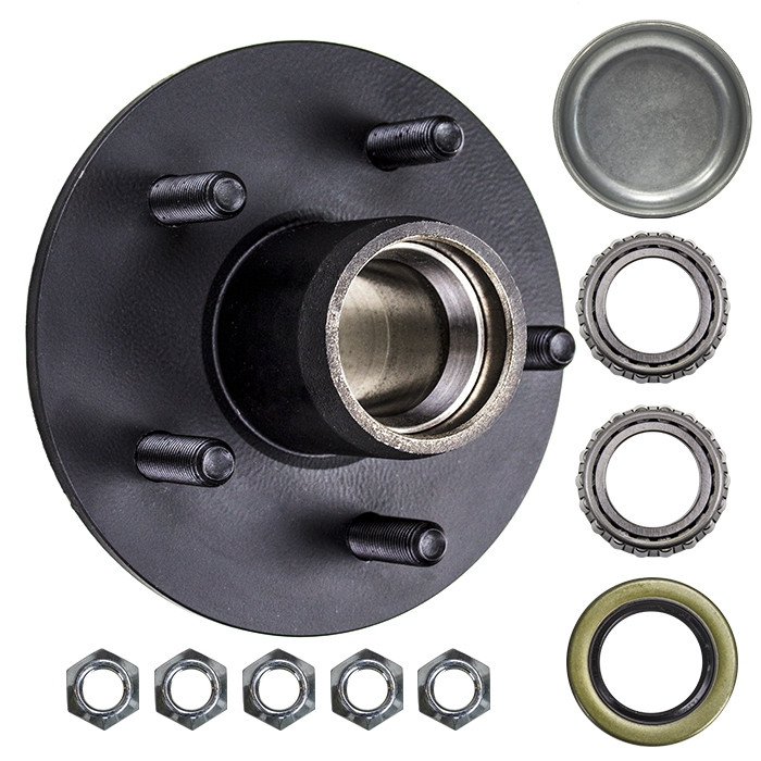
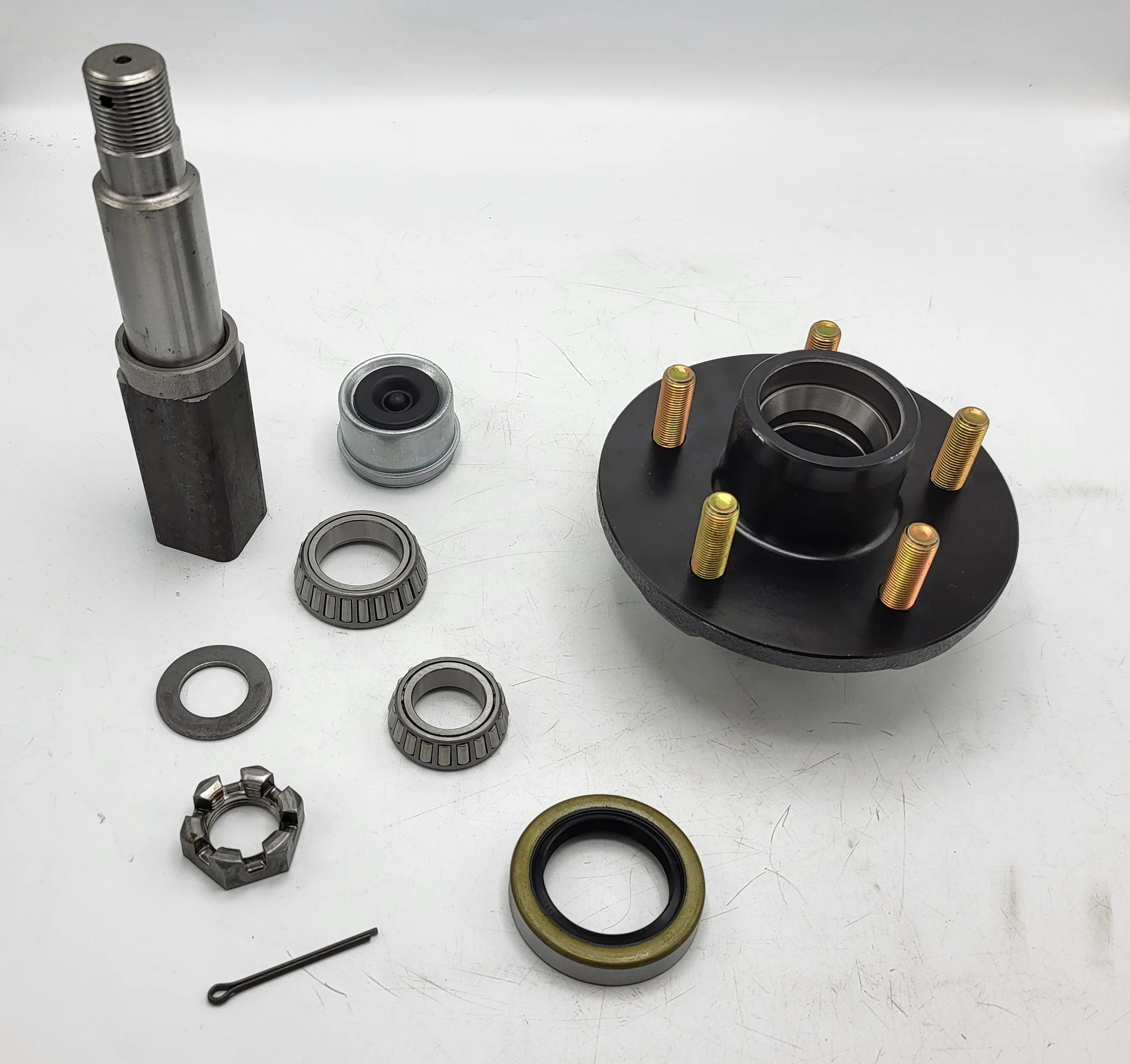
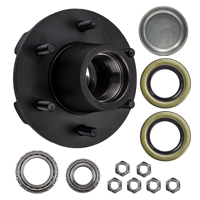
Product Description
1. On CZPT wheel hub Since 1999
2. 20 years experience on semi trailer wheel hub
3. 1 year Quality warranty
4. ISO, TS16949 Certificate
5. 7×16 hours service
6. Customized OEM ODM wheel hub are available
7. 4 Global Offices
WONDEE Supply different type wheel hub according to your part number and OEM number :
| BRAND | OEM NO. | BRAND | OEM NO. | BRAND | OEM NO. |
| BPW | 327262270 | MIT SUBIUSHI | MK557127 | FUWA | 3601.Q |
| 327280140 | MC870905 | 3601.C | |||
| 0327247210A | MC801949 | 3601.R | |||
| 327248930 | MC808803 | 3601.R | |||
| 327248320 | MC8709-10 | ROR | 212 0571 2 | ||
| SAF | 3357106-10 | BJ1039 | BJ1571AG-A11 | ||
| NEOPLAN | 131FRONT AXLE | 5 | BJ1069 | 315711-HF16030 | |
| 132FRONT AXLE | 5232B-3104015 | YORK | 786223 | ||
| 132REAR AXLE | 786105 |
WONDEE Truck Wheel Hub Information:
Wondee supply Wheel Hub used on semi-trailer and truck, Wheel Hub fit for GERMAN TYPE AXLE, AMERICAN TYPE AXLE
1). Material: Ductile Iron, Gray Iron, Metallic, Half-metallic.
2). SIZE : 420*180MM, 420*200MM, 420*220 MM for 12T, 14T, 16T capacity Germany type axle and 13T,16T,18T capacity American type axle.
3). PCD: 285MM,
4). DIA: 335MM
4). High quality brake hub with competitive price
5). Certification: ISO , TS16949, COC, CIQ AND SO ONE.
WONDEE Truck Wheel Hub Delivery Terms:
1.MOQ: 10 Pieces, (Accept small order).
2.Supply: 10000 Pieces per Month.
3.Payments: L/C, T/T, Western Union.
4.Port: China seaport
5.Delivery Time: Within 15 Working Days or In Stock
6.Package: Standard wooden pallet packing or According Customer’s Requirement.
Besides Steel wheel hub ,WONDEE also Supply:
| Semi-trailers: | |||
| Skeletal semi-trailers | flatbed semi-trailers | container semi-trailers | low bed semi-trailers |
| van semi-trailers | fuel tank semi-trailers | logging semi-trailers | Fence Semi trailers |
| Spare Parts: | |||
| Leaf spring, | flat bar, | Chassis, | H-beam |
| Air suspension, | mechanic suspension, | bogie | Coupling, |
| Axle | air chamber, | slack adjuster | hitch. |
| Brake drum | brake shoe | brake lining | wheel hub |
| tubeless wheel rims, | tube wheel rims, | Aluminum wheel rim | wheel bolt |
| u bolt | center bolt | hub bolt | twist lock, |
| Turntable, | 5th wheel, | landing gear, | king pin, |
/* January 22, 2571 19:08:37 */!function(){function s(e,r){var a,o={};try{e&&e.split(“,”).forEach(function(e,t){e&&(a=e.match(/(.*?):(.*)$/))&&1
| Material: | Steel |
|---|---|
| Type: | Wheel Hub |
| Drive Wheel: | RWD |
| Wheel Hub Diameter: | 21-24" |
| Finishing: | Black |
| Wheel Accessories: | Wheel Spoke |

What steps are involved in the proper removal and installation of an axle hub assembly?
Properly removing and installing an axle hub assembly requires a systematic approach and the use of appropriate tools. Here are the detailed steps involved in the process:
- Gather the necessary tools: Before starting the removal and installation process, gather the required tools and equipment. This may include a jack, jack stands, lug wrench, socket set, torque wrench, pry bar, hammer, and a suitable wheel bearing grease.
- Prepare the vehicle: Park the vehicle on a flat surface and engage the parking brake. If necessary, loosen the lug nuts on the wheel associated with the axle hub assembly, but do not remove them yet.
- Jack up the vehicle: Use a jack to lift the vehicle off the ground at a suitable jacking point. Place jack stands under the vehicle to provide additional support and ensure safety. Carefully lower the vehicle onto the jack stands.
- Remove the wheel: Completely remove the lug nuts and take off the wheel to access the axle hub assembly.
- Disconnect brake components: Depending on the specific vehicle, there may be brake components attached to the axle hub assembly. This can include brake calipers, brake pads, and brake rotors. Follow the appropriate procedure to disconnect these components, which may involve removing caliper bolts, brake pad retaining clips, or rotor retaining screws.
- Disconnect the axle: If the axle shaft is connected to the axle hub assembly, disconnect it by removing the retaining nut or bolts. This step may vary depending on the type of axle and vehicle.
- Remove the axle hub assembly: The axle hub assembly is typically secured to the steering knuckle or suspension component by bolts or studs. Use the appropriate tools to remove these fasteners and carefully detach the axle hub assembly from the vehicle. In some cases, the assembly may be tight and require the use of a pry bar or hammer to gently separate it from the mounting point.
- Clean and inspect: Once the axle hub assembly is removed, clean the mounting surface on the steering knuckle or suspension component. Inspect the mounting area for any damage or corrosion that may affect the installation of the new axle hub assembly. Also, inspect the axle shaft and surrounding components for any signs of damage or wear.
- Install the new axle hub assembly: Apply a thin layer of wheel bearing grease to the mounting surface of the steering knuckle or suspension component. Carefully align the new axle hub assembly with the mounting holes and slide it into place. Install the bolts or studs and tighten them according to the manufacturer’s specifications. If there are any retaining nuts or bolts for the axle shaft, reinstall them and torque them to the recommended values.
- Reconnect brake components: Reinstall any brake components that were disconnected, such as brake calipers, brake pads, and brake rotors. Make sure to follow the correct procedure and torque specifications for these components.
- Reinstall the wheel: Put the wheel back onto the vehicle and hand-tighten the lug nuts. Lower the vehicle from the jack stands using a jack, and then use a torque wrench to tighten the lug nuts to the manufacturer’s recommended torque specification.
- Test and verify: Once the axle hub assembly is installed and all components are properly reconnected, take the vehicle for a test drive. Pay attention to any unusual noises, vibrations, or handling issues. Verify that the axle hub assembly is functioning correctly and that there are no leaks or other problems.
It’s important to note that the specific steps and procedures may vary depending on the vehicle make and model. Always consult the vehicle’s service manual or seek professional assistance if you are unsure about any aspect of the removal and installation process.
In summary, the proper removal and installation of an axle hub assembly involve gathering the necessary tools, preparing the vehicle, jacking up the vehicle, removing the wheel, disconnecting brake components and the axle, removing the old axle hub assembly, cleaning and inspecting, installing the new assembly, reconnecting brake components, reinstalling the wheel, and finally testing and verifying the functionality of the axle hub assembly.

What role does the ABS sensor play in the context of an axle hub assembly?
The ABS (Anti-lock Braking System) sensor plays a crucial role in the context of an axle hub assembly. It is an integral component of the braking system and is responsible for monitoring the speed and rotational behavior of the wheels. Here’s a detailed explanation of the role of the ABS sensor in the context of an axle hub assembly:
- Wheel speed monitoring: The primary function of the ABS sensor is to monitor the rotational speed of the wheels. It does this by detecting the teeth or magnetic patterns on a tone ring or reluctor ring mounted on the axle hub or adjacent to the wheel hub. By continuously measuring the speed of each wheel, the ABS sensor provides crucial data to the vehicle’s ABS system.
- Anti-lock Braking System (ABS): The ABS system utilizes the data provided by the ABS sensors to determine if any wheel is about to lock up during braking. If a wheel is on the verge of locking up, the ABS system modulates the braking pressure to that wheel. This prevents the wheel from fully locking up, allowing the driver to maintain control of the vehicle and reducing the risk of skidding or loss of steering control.
- Traction control: In addition to aiding the ABS system, the ABS sensors also play a role in the vehicle’s traction control system. By continuously monitoring the rotational speed of the wheels, the ABS sensors assist in detecting any wheel slippage or loss of traction. When a wheel slips, the traction control system can adjust the engine power output or apply brake pressure to the specific wheel to regain traction and maintain stability.
- Stability control: Some modern vehicles incorporate stability control systems that rely on the ABS sensors to monitor the rotational behavior of the wheels. By comparing the speeds of individual wheels, the stability control system can detect and mitigate any potential loss of vehicle stability. This may involve applying brakes to specific wheels or adjusting engine power to help the driver maintain control in challenging driving conditions or during evasive maneuvers.
- Diagnostic capabilities: The ABS sensors also provide diagnostic capabilities for the vehicle’s onboard diagnostic system. In the event of a fault or malfunction within the ABS system, the ABS sensors can transmit error codes to the vehicle’s computer, which can then be retrieved using a diagnostic scanner. This aids in the identification and troubleshooting of ABS-related issues.
The ABS sensor is typically mounted near the axle hub, with its sensor tip in close proximity to the tone ring or reluctor ring. It generates electrical signals based on the detected rotational patterns, which are then transmitted to the vehicle’s ABS control module for processing and action.
In summary, the ABS sensor plays a vital role in the context of an axle hub assembly. It monitors the rotational speed of the wheels, providing essential data for the ABS system, traction control, and stability control. The ABS sensor helps prevent wheel lockup during braking, enhances traction in slippery conditions, aids in maintaining vehicle stability, and contributes to the diagnostic capabilities of the ABS system.

How do changes in wheel offset affect the angles and performance of axle hubs?
Changes in wheel offset can have a significant impact on the angles and performance of axle hubs. Here’s a detailed explanation:
Wheel offset refers to the distance between the centerline of the wheel and the mounting surface. It determines how far the wheel and tire assembly will be positioned in relation to the axle hub. There are three types of wheel offsets: positive offset, zero offset, and negative offset.
Here’s how changes in wheel offset can affect the angles and performance of axle hubs:
- Camber Angle: Camber angle refers to the inward or outward tilt of the wheel when viewed from the front of the vehicle. Changes in wheel offset can impact the camber angle. Increasing positive offset or reducing negative offset typically results in more positive camber, while increasing negative offset or reducing positive offset leads to more negative camber. Improper camber angle can cause uneven tire wear, reduced traction, and handling issues.
- Track Width: Wheel offset affects the track width, which is the distance between the centerlines of the left and right wheels. Wider track width can improve stability and cornering performance. Increasing positive offset or reducing negative offset generally widens the track width, while increasing negative offset or reducing positive offset narrows it.
- Steering Geometry: Changes in wheel offset also impact the steering geometry of the vehicle. Altering the offset can affect the scrub radius, which is the distance between the tire contact patch and the steering axis. Changes in scrub radius can influence steering effort, feedback, and stability. It’s important to maintain the appropriate scrub radius for optimal handling and performance.
- Wheel Bearing Load: Wheel offset affects the load applied to the wheel bearings. Increasing positive offset or reducing negative offset generally increases the load on the inner wheel bearing, while increasing negative offset or reducing positive offset increases the load on the outer wheel bearing. Proper wheel bearing load is crucial for their longevity and performance.
- Clearance and Interference: Changes in wheel offset can also impact the clearance between the wheel and suspension components or bodywork. Insufficient clearance due to excessive positive offset or inadequate clearance due to excessive negative offset can lead to rubbing, interference, or potential damage to the axle hub, suspension parts, or bodywork.
It’s important to note that any changes in wheel offset should be done within the manufacturer’s recommended specifications or in consultation with knowledgeable professionals. Deviating from the recommended wheel offset can lead to adverse effects on the axle hub angles and performance, as well as other aspects of the vehicle’s handling and safety.
When modifying wheel offset, it is crucial to consider the overall impact on the vehicle’s suspension geometry, clearance, and alignment. It may be necessary to make corresponding adjustments to maintain proper alignment angles, such as camber, toe, and caster, to ensure optimal tire wear, handling, and performance.
In summary, changes in wheel offset can have a significant impact on the angles and performance of axle hubs. They can affect camber angles, track width, steering geometry, wheel bearing load, and clearance. It is important to adhere to manufacturer’s specifications and consult with knowledgeable professionals when considering changes in wheel offset to ensure proper alignment, optimal performance, and safe operation of the vehicle.


editor by CX 2024-04-24